|
|
Post by kvom on Jan 27, 2013 20:38:56 GMT -5
After a couple of weeks away from home, I spent an afternoon in the shop with the A3. Propped the loco frame on some riser blocks to get the wheels off the rails, and was able to mount the brake assembly. Everything is a tight fit, so not too easy. Anyone who builds the brakes and is ready for a final assembly will be advised to install them before any valve gear or rods.
Next I re-installed three of the spring packs. The springs are quite strong, so I found the best way to do the rear pair was to install them on the hangers with one hanger unattached to the frame. Then I could press down enough to start the screws for the other hanger and let the screws compress the springs. I also found that installing the back hangers for the front drivers was a real PITA. The drivers keep you from inserting the lower pins from the outside, so I had to finagle installing the tiny e-clips using needle nose pliers and strong language. These hangers should be mad and installed early in the assembly process, before the drivers and axles. Got one spring pack on and found that one of the retainer clips for the other is missing. So that's a little fab job for tomorrow. With the springs installed I'll be able to put on the boiler and smokebox to start laying out the piping.
|
|
|
|
Post by kvom on Feb 3, 2013 15:18:28 GMT -5
I got the springs mounted and then put on the boiler and smoke box. With that weight the axle boxes are close to the center of the their travel range, which seems likely is the design point. Here's a pic afterwards:  The fact that the boiler drawing put the steam dome 2" too far forward is going to make the loco look mis-proportioned, even with the sand dome moved forward as shown. The bell will end up very close to the smoke box. The throttle tube is higher and thicker than Kozo's drawing, so I'll need to modify the front wall of the cab to fit eventually. In any case the club boiler hydro-tests are next month; since I've now drilled all the holes into the boiler that are needed I'll be ready for steam-up afterwards if I can get the piping done. |
|
|
|
Post by kvom on Feb 4, 2013 17:51:00 GMT -5
I made a start on the turret today. The body of the turret is a piece of 360 brass, 3/4x1.25x4". Drilled the two holes for mounting to the throttle tube and drilled/reamed the 1/2" center hole for the throttle rod gland. My design for the gland derives from that used for the valve rods, using a Viton o-ring for sealing the 1/4" SS throttle rod. The gland itself is two-piece, the larger brass piece fitting into the turret hole and the smaller bronze piece fitting the larger. The two pieces leave a pocket for the o-ring. This design will allow me to remove/install the 2-piece throttle rod and the valve crank without removing the turret itself.  With the parts assembled, the back view: 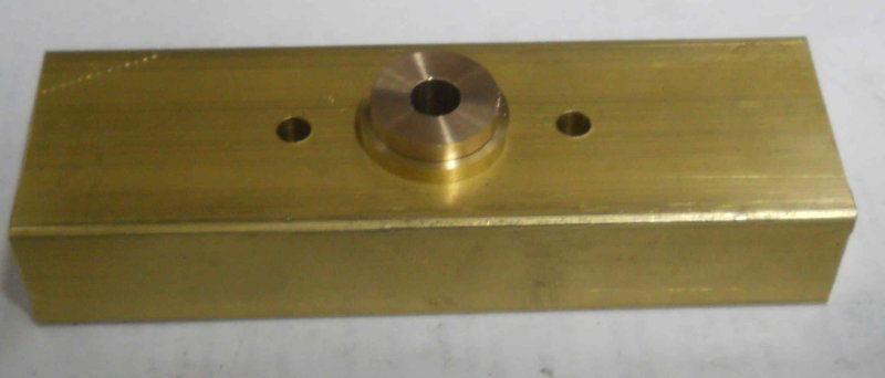 This view of the front shows how the cross-drilled hole will intersect the main steam passage to supply the injectors while missing the mounting holes. Any other valve holes will intersect the cross passage.  |
|
|
|
Post by silversanjuan on Feb 5, 2013 11:17:01 GMT -5
It's great to see the boiler on the frame! Hope the hydro goes well.
|
|
|
|
Post by kvom on Feb 5, 2013 14:35:47 GMT -5
The boiler minis the dome was hydroed a year ago, so I don't expect any problems this time. Today I drilled the cross passage in the turrent without a problem, using a C drill bit from each end (C is the tap drill for 1/16 NPT). Then I assembled the turret block and rear flange on the loco for a test fit (the rear flange needs to be marked on the throttle tube before soldering so that the turret is horizontal).  Then I discovered a problem: The right end of the turret is even with the reversing lever when at full forward, and there's not enough room for the injector valve and a pipe union. I'll have to decide what to do about that. |
|
|
|
Post by kvom on Feb 7, 2013 16:28:14 GMT -5
Did a few minor tasks in the shop today. I had to take the boiler and smokebox off the chassis as I need to remove the rear footplate. It will need to be counterbored for the drawbar pin as the head of the pin interferes with the fire door. I attached the brake pedal and reach rod in order to get an idea of how I'd mount the injector at the rear of the frame. There's a lot of "stuff" in that area: blowdown valve, ashpan latch, and the foot pedal. Looks like it will just fit without being too far forward. I don't want it too close to the rear driver as that would mean a sharp curve in the water supply pipe. I did a test fit on the left side, where there is nothing to interfere but the blowdown valve. With the valve clamped to the frame in its approximate position, I ended up with this:  I drilled a second hole in the bracket to move it higher, as shown. The bottom of the injector is still only about an inch above the rails. I'll probably try a bit of an s-curve on the copper tube to position the injector a bit higher. |
|
|
|
Post by kvom on Feb 8, 2013 19:14:03 GMT -5
After some advice from a number of other builders, I believe I have located the "best" spot for the injectors; the water inlet will be about level with the top of the frame, and as far back as I can get it. I have some ideas about routing the water input but will have to experiment a bit before finalizing the plan. In the meantime I built a pair of parts that will connect the Locoparts blowdown valves to the boiler. On the .75" scale model, the single valve is screwed into the boiler directly with no frame in the way. On the 1.5 scale version, he specifies a single valve going through the left frame only. I will have a blowdown on both sides, and rather than build them I purchased a pair from Locoparts. The male pipe thread on these is too short to pass through the frame and screw into the boiler, so an extension is needed. Originally I was thinking that a short nipple and a bushing would be the easy way to go, but today I decided to just make each as a single brass part. Here's the result:  These will position the valve outboard of the frame about 3/4 of an inch so that the lever will now be under the walk board. This will allow me to attach a lifter that passes through the board and that can be activated when the locomotive is moving. It should also be possible to route the water feed line to the injectors behind the valve rather than in front. I also countersunk the hole in the rear footboard so that the draw bar pin is recessed and no longer interferes with the fire door. |
|
|
|
Post by kvom on Feb 13, 2013 15:35:31 GMT -5
Built a mockup of my throttle design to check the geometry. It looked good when I drew it in Draftsight, but I needed to make sure the movement was at least fairly smooth. Seems to be good, and I get the 2" travel needed to open the valve full closed to full open with a 1" crank.  |
|
|
|
Post by kvom on Feb 24, 2013 19:57:10 GMT -5
I got quite a bit done over the weekend, esp. since the Jeep is awaiting parts elsewhere and there is room in the shop. Since the club's hydro test day is coming up next month, I decided to plug as many holes as possible in the boiler. So in addition to actual plugs, I also screwed in the blowdown valves and boiler checks. I discovered that for a boiler check I needed to either do it before putting the boiler on the chassis, or else remove the walkboard. I ended up putting one of the boiler checks into the glass gauge hole. In any case, the 4 valves will get tested for leakage. I also drilled and tapped a 1/4 NPT hole in the steam dome cover. This will be the water fill point. After installing the throttle valve in the steam dome, I proceeded to try to finish the throttle reach rod. This is a 2-piece rod with a brass joint, similar to how the inner piece attaches to the throttle crank. After making the connector pin from brass, I decided to use brass cotter pins rather than the steel latch pins to retain them. Seems the latch pins would rust. The outer piece was left long and the turret attached. Here's the throttle valve installed:  And the unfinished rod installed.  Now I was able to mark the rod for length, remove it, cut, and thread the end 1/4-20. The rod material is 304 SS. Now after reassembly I could test the action of the throttle. It seems pretty smooth. I need to remake the "fork" that screws onto the rod. Here's the finished rod:  And the throttle assembled:  The next task was to work on the transport board for toting the loco and tender in my truck. It's a 4x8 sheet of outdoor plywood that had 3 coats of outdoor paint. Hopefully it will hold up since I will probably leave it outside in the truck bed most of the time. In any case, I put it on the auto lift and raised it until I could roll the A3 onto the board. With it and the tender positioned so that the tender's coupler is just inside the end of the rail, I positioned a retainer I made from an old steel angle block.  The retainer is bolted to the board with a couple of 1/2" screws, and attaches to the loco's coupler pocket. With the rolling stand freed up, I took the opportunity to paint it. I still need to make a pair of hold downs on the board for the loco and tender. I';; use a ratchet strap for the tender, but need to think a bit for the loco. If the weather hold up I plan to take it to the club this week for a tow around the yard and to test the foot brake. |
|
|
|
Post by kvom on Feb 26, 2013 15:08:27 GMT -5
Today I added tender tiedowns to the carry board. These are 2" ubolts on each side secured by bolts on either side plus a metal strap underneath. With the loco and tender on the board, here's the travel setup: 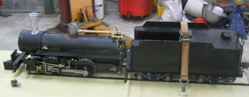 The big ratchet strap is not cinched at all as it could easily bend the sides of the tender. The loco is restrained by the coupler pocket at the front and the drawbar at the rear, so for now I think it's OK for travel. I'll consult with other club members on this. With the board on the ground, I was able to sit on the tender and check out the ergonomics. The foot brake pedal is easy to reach, as are the reverse and throttle levers. As well, the intended position for the injector valves are easy enough to reach. The pressure gauge will likely end up behind the turret with the face angled up. I'm don't think it will be very easy to see the fire that well without leaning way down, so I'll have to wait. Here's the view from the cab:  As can be seen, the throttle links will interfere with the water glass. I think the best solution may be to have a 1" nipple and bushing in the backhead and thus move the glass backwards to clear. The valve for the blower looks like it will fit fine just above the through stay. |
|
|
|
Post by kvom on Feb 26, 2013 17:06:26 GMT -5
After posting the previous message, I decided I could make an extension off the backhead myself similar to the extension for the blowdown valves. A short time later:  |
|
|
|
Post by kvom on Mar 4, 2013 18:00:24 GMT -5
Started planning the inject valve piping. I used Draftsight to draw the tube, elbow, valve, and union on each side of the turret. I then printed at actual size and laid onto the turret to see how things look. I made some adjustments and ended up with this:  |
|
|
|
Post by kvom on Mar 5, 2013 16:59:35 GMT -5
Started on the turret piping for the injector valves today. I discovered that the cross passage in the turret is too close to the edge to allow enough threads for a 1/16NPT connection. So I drilled and tapped some 3/8" brass round bar, then milled 3/8 holes in the turret. The bars will be soldered into the turret, and the elbows screwed into them. Here's where I left off this afternoon. Next shop session I'll solder the connections. The straight sections are 5/16" OD thick wall brass pipe I got at Cabin Fever last year, along with the PMR bronze elbows. The pipe is hard to thread as the die gives very stringy chips. I have some 5/16 hard copper tube that can be threaded and might have worked better. I'll try that on the next connections, which will be between the valves and the unions.  |
|
|
|
Post by kvom on Mar 20, 2013 21:19:55 GMT -5
Started piping work on the left-side injector. The steam inlet pipe from the turret holds it in place for fitting the water pipes.  The water inlet pipe shown is just a "trial" using hand-bent copper tube. I need to borrow a tube bender as the tube shown won't work properly. After taking the pic I took the turret and this part down to seal up the boiler for hydro this Saturday. |
|
|
|
Post by kvom on Mar 23, 2013 20:55:12 GMT -5
We had annual boiler hydro testing at the club today, and I'm happy to say my boiler passed. The only leak was a pinhole in the TIG weld at the side of the steam dome, and some peening with a punch closed it up. Tested at 200 psi. The only downer was that neither of the Locoparts boiler check valves worked. They were completely open when filling the boiler (no pressure). So I took them off and inserted plugs. The gaskets I made for the steam dome and throttle sealed perfectly. I made them from paper gasket material purchased at Ace Hardware, and used a mixture of steam oil and powdered graphite as the sealant.
I'll open up the check valves tomorrow to try to see why they're completely open to water flow.
|
|

