|
|
Post by GregMiller on Jan 10, 2010 19:33:56 GMT -5
Pat, Nice update to your website! When you applied soft solder to the halves, then pressed them together, did you need to heat the 2 halves again as pressure was applied, or did the solder remain molten long enough to get them situated and pressed? I starting with the 2.5" diameter round of bronze, and cutting into the 8(well, 12 after I remade 2  ) pieces. Aside from the added cost, your approach starting with the 1" round is quicker. Greg |
|
|
|
Post by phutcheson on Jan 11, 2010 2:04:24 GMT -5
grege,
Thanks for the the input ... still moving on ... really hope to get more done this year then I did in 2009! 
Harlock,
Chloe really looking good. Do you plan on taking her to the Bitter Creek meet in August 2010. Sure would like to hitch a ride around the track! 
Greg Miller,
Thanks for the nice words.
After I applied the solder I removed as much as I could so that only a thin coat was left. Let them cool down, matched them up, applied heat and pressure to squeeze out excess solder.
2 1/2" bronze bar ... that's a big chuck of material. My only concern was that I had enough material for the lip diameter. The 4 sides were only as wide as needed for the jaws.
All ...
It is really great that you guys and others post their photos ... a real inspiration to continue!
Later,
Pat H
|
|
|
|
Post by Harlock on Jan 11, 2010 2:50:49 GMT -5
grege,
Harlock,
Chloe really looking good. Do you plan on taking her to the Bitter Creek meet in August 2010. Sure would like to hitch a ride around the track!
That's the plan...come on down...bring your A3 bits too for show and tell, I'm sure Jack would love to see progress. The Chloe will be done probably sometime this spring. --Mike |
|
|
|
Post by phutcheson on Sept 1, 2010 17:29:21 GMT -5
Well ... finally did an update to my Web site on the A3 Progress. Been working on her ... but not reporting until now.
Things are moving along ... slow but sure
Updated Driver Wheels and added Side Main Rods and Cylinders.
Now the Pistons ...
Enjoy,
Pat H
|
|
|
|
Post by pkastagehand on Sept 3, 2010 12:57:41 GMT -5
Lookin' good. CNC really makes doing the rods look easy!!
Not intending to be snide or be a "rivet counter" but one comment is the flat face of the spokes in the wheels. I'm not sure if you could have done any different or if so how. Corner rounding endmill?
Paul
|
|
|
|
Post by grege on Sept 8, 2010 6:59:36 GMT -5
Nice progress! Parts are looking good.
It's fun to see a different approach to making the same parts I have labored over.
|
|
|
|
Post by phutcheson on Sept 8, 2010 18:23:00 GMT -5
Paul ...
CNC has been fun to use ... I have milled the profile on most of the valve gear linkage and reverse gear linkage back in February/ March. Still need to pull them out of the raw flat stock and mill them to size and finish. One great benefit ... easy to make extras. I usually will make 1 to 2 extra just in case.
As far as the Drivers looks with the flat face ... looks good. Makes them look bigger (I guess they are in a way) and stronger. At the time I was just beginning CNC so I was anxious and really didn't know what to do plus I had spent a lot of time on them ... just wanted to get them done. Next time I think I would put a small radius using a round endmill. But then again ... that bold flat surface does look good.
Grege...
That's what make this and other sites nice to use ... you can see what others are doing. I review about 5 different sites to see what's going on ... if I see something that helps ... I will try it!
Back to the pistons ... man, 1st one use easy ... the next 3 were scrap  ... but finally got it! ... but finally got it! 
Later,
Pat H
|
|
|
|
Post by phutcheson on Oct 8, 2010 19:01:02 GMT -5
Well ... surprise another update on my A3 progress ... the Pistons and Crossheads! Only a few scraps pieces .... there is not much room for errors for those parts.
For the Piston I followed Ed Hume suggestion ... if I calculated right the O-ring squeeze is about 6.6%. I read in Kozo's Building the New Shay where he Loctites the Pin and Rod. Interesting ... I wonder if that helps reduce the steam leaking through the cracks?
The Crossheads ... I was concerned about silver soldering SS303, but they came out great. I used the Black Flux and 45% Silver Alloy from McMaster Carr. Results were terrific and easy to do ... I only had to be careful with the Cadmium fumes. 
Getting close to running on air. But next are the Tie Plate and Yokes . We are having fun!
For more information and details check out my site (see below) under Projects.
By the way can someone give me the steps to post a few pictures here? I was able to get one posted, but it was way too big. Tried again but lost the sequence.
Also ... it sure has been quiet ... what's everyone doing?? 
Enjoy,
Pat H
|
|
|
|
Post by grege on Oct 11, 2010 7:06:12 GMT -5
Nice progress on your pistons and crossheads. The crossheads are a bit fiddly. So many operations with potential to create scrap along the way. I've been continuing to slowly make boiler parts. I'm about ready to start rolling the main barrel, around a pipe since I don't have a roller. 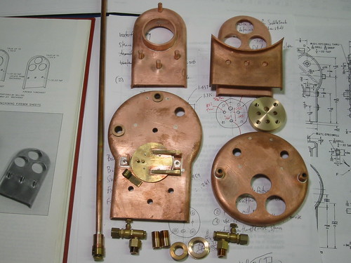 Soldered backhead and bushings Soldered backhead and bushings by gregeaster, on Flickr |
|
|
|
Post by ramkitty on Oct 12, 2010 11:56:49 GMT -5
wow, looking really good grege and phutcheson.
I have finished my tender wheels (polishing and painting now) and bought most of the mat for the tender and the start of the loco. Using the combo mill-lathe at work it is a huge pita to switch tasks so I am doing as much on one tool before switching to another tool. I have prepped a lot of material for the milling machine including the 1/16 sheet parts for the steps and columns.
I am waiting for the sheet metals to arrive as well as some more stock like the brass hex rod and the mats for the bolsters and tender frame which I will have to up size to 3/8ths thick.
I need to find a source for some of the brass screws but I see that 2 links were given here recently for hex head screws.
Also a mini lathe with the dro handles came up on a local classifieds page and I am thinking of snaging it up for a reasonable price which would allow me to do mostly milling on the combo tool. My main concern is that it may be too small at 7x12
|
|
|
|
Post by doug on Oct 12, 2010 19:45:23 GMT -5
Grege,
Nice looking boiler parts. What size are the tubes?
Doug.
|
|
|
|
Post by grege on Oct 12, 2010 20:25:12 GMT -5
ramkitty- good to hear your progress. I have an 8x14 lathe, but only a few parts need the larger size so you might be fine if you have access to a larger machine.
doug- tubes are .750" OD with a .062" wall. Specified on the boiler drawing was the equivalent of 20mm (.787), though another drawing noted .755 for the holes... I couldn't find the metric size. I found a spreadsheet on another fellow's site that calculated approximate tube area for a given grate, and the .750 was in the adequate range for good draft/steaming.
|
|
|
|
Post by kenrinc on Oct 13, 2010 16:32:21 GMT -5
Keep us abreast of the Oring fit. I have yet to find an O-ring that meets the so called "spec" using Kozo's article from the New Shay. It's more than a trivial process. The ones I bought for the valve rod were too small and another set were smaller still. I had to fit a sleeve and recut with a long custom tool to fix. Lame.
Ken-
|
|
|
|
Post by phutcheson on Oct 14, 2010 13:34:32 GMT -5
Thanks for all the replies ...
Grege ...
Great to see your progress on the boiler. It's coming together real nice. Where are you getting the tubes?
Did you have any issues with your O-rings for the piston/valve?
kenrinc had a great deal of problems. But I haven't heard about it before.
Any issue that I might be able to avoid for the valve gears assembly ... looks like a lot of pieces have to go together just right?!
By the way ... how do you post a picture here?
ramkitty
Thanks and sounds like you a preparing your work in advance ... good planning. Seem like I'm always waiting for material.  Do you have any pictures of your A3? Do you have any pictures of your A3?
kenrinc
You have had some real issues with the O-rings ... what kind did you use and where did you buy them?
Can you post a picture of your sleeve?
Back to my Guide Yoke assembly ... appears that there are a lot of critical mounting hole locations necessary so that the Valve Gear linkages will line up just right! This will be interesting!
Later,
Pat H.
|
|
|
|
Post by kenrinc on Oct 14, 2010 16:17:19 GMT -5
I should clarify. I'm building in 1.5" scale but you adjust the O-ring accordingly. I used the new shay o-ring article for that. I've found that what Kozo shows in the tables for squeeze diameter, that is, the actual dimension that needs to be bored, the o-rings would just fall into. Wouldn't even touch the sides. I'm not faulting Kozo, I'm faulting the fact that I don't think there really is a standard. If you look at some of these things under a microscope you'll see what I mean. And there is no way to measure an o ring, per se....
The sleeve: that was just over boring and then pressing in a rod and re drilling/borring. In other words, starting over.
Ken-
|
|

 ) pieces. Aside from the added cost, your approach starting with the 1" round is quicker.


 ... but finally got it!


