|
|
Post by kvom on Jun 28, 2011 14:41:54 GMT -5
Back at it after some family vacation time. I finished the machining of all the spring hangers from pg. 210.  I made this harder than it needed to be. If I can remember not to try to cut slots with a 4-flute endmill and not to reply on cheap Chinese 1/8" carbide endmills for anything, things might go better in the future. Still to do is round the edges that go through the spring slots, heat and twist two of the hangers 90 degrees, and turn all of the pins that hold it all together. I also need to remake the spring bands (pg. 209). I find that with the springs cambered they don't fit through the opening. Rather than as drawn, I'm going to make the tops open with a cap. |
|
|
|
Post by powderhorn01 on Jun 29, 2011 21:21:05 GMT -5
Kvom:
For hogging slots, I like to use a roughing end mill, they seem to cut easier, and less chater.
|
|
|
|
Post by kvom on Jul 3, 2011 16:15:35 GMT -5
With the hangers machined, I now needed only the gibs (spring retainers) to make before trial fitting. While the gibs are pretty simple, I find making them a bit tedious as they are small.  Both the gibs and hangers needed to have rounded edges to fit through the slots milled in the spring bands. It would have been better to have made the slots longer than per plan, as that way the rounding wouldn't be necessary. As it was, I held the parts with a vise-grip and worked on them via the grinding wheel. Not pretty, but it works. The hangers that attach to the equalizer beam needed to be twisted 90 degrees. I clamped them in the bench vise, heated with a MAPP gas torch, and twisted with a large wrench. Since I haven't made any of the pins that hold it all together, I just did a trial fit using screws.  I haven't put any camber into the spring leafs as yet. With just the frame weight, the flat springs support the axles with about 1/4" of up travel remaining. With the boiler/water and everything else there's about another 100 pounds left to support, so I need to put that amount of weight on and add spring camber to suit. The ideal height should have the cylinder centerline level with the axle centers. The spring bands won't get tops until I know how much camber I need. |
|
|
|
Post by kvom on Jul 5, 2011 18:58:47 GMT -5
Today was my first experience with e-clips, which Kozo uses extensively to retain pins. A majority of the pins used in the spring and brake rigging are 5/32" diameter. Unfortunately my 5C collet set is by 16ths, so I started with the few pins in the spring setup that are 3/16". The groove for the clips is spec'ed at .029 wide; I had a grooving tool that I ground for cutting cylinder fins on the Liney Halo, and it turns out that this works well. My "test" pin connects the brake equalizer with the cross member via two short hangers.  There are about 2 dozen 5/32 pins to do, and only the rubberflex chuck will hold that diameter. I'm going to order a 5/32 5C collet since I want to cut the groove close to the chuck face. In retrospect, I think almost all of these pins could be made with 3/16 drill rod. |
|
|
|
Post by kvom on Jul 9, 2011 11:03:09 GMT -5
The order from Enco came yesterday so I now have a 5/32 5C collet for making the rest of the spring/brake pins. I also got two sheets of acrylic and a gallon of coolant, so I want to finish setting up the coolant pump and shield before using the CNC mill again. Once that's done, the next parts to be milled will be the crossheads. Yesterday I visited the local steelyard and picked up this chuck of CRS (1x2.5x6) from which two crossheads will be milled together.  I milled off the torch slag with a roughing endmill, then cleaned up 5 sides with a face mill.  |
|
|
|
Post by kvom on Jul 9, 2011 20:57:11 GMT -5
Doing some "experiments" with a length of DOM tube that might work out as the smokestack. I don't have a steady rest for the lathe, nor a bull live center, so this is my substitute. I took a piece of 2" aluminun, turned a 60-degree taper one end and center drilled the other. So it supports the tube for external turning. I don't know if I can turn the internal taper with the end unsupported, however.  In any case, the smokestack won't be needed for quite some time. |
|
|
|
Post by kvom on Jul 10, 2011 19:14:13 GMT -5
Over the weekend I finished up all the e-clip pins that hold the spring hangers and brake levers together:   14 pins for springs and 20 for brakes. There are a number of similar ones still to do for the valve and reverse gear. |
|
|
|
Post by pkastagehand on Jul 11, 2011 9:09:04 GMT -5
This is where a CNC lathe could be useful. I hate turning pins. (of course I get bored if I have to make more than one of most parts)
Nice work, keep it up!
Paul
|
|
|
|
Post by kvom on Jul 11, 2011 10:00:42 GMT -5
I got into a sort of rhythm doing these, and a collet chuck + DRO helps a lot. First op on each pin is with a 1/16" parting tool. 1) use file to chamfer end of stock 2) open collet, pull out enough drill rod for the next pin 3) position DRO at the end and zero X 4) move carriage required length and part repeat as needed Op2 is also with the parting tool insert pin into collet and cut off the tit remaining from parting chamfer end with file Op3 is with grooving tool. touch tool to first pin and set Y to stock diameter. Then for each pin: insert into collet touch tool to end of pin and zero Z move carriage left .074 cut groove to diameter per plan using Y DRO light pass with file to deburr the groove reverse in collet to do other end I think my total time for all the pins was about 4 hours We had workers all morning tearing up half the kitchen floor wood (refrigerator leaked), so only a short time in the shop today. I fit together the bits of the brake system that use pins and e-clips to test for fit (pg. 213 in Kozo book). I need to remake one pin that's a bit short.  The two links that connect to the break beam are probably a bit too tight fitting, even with some grinding and filing. I need to get the return springs to see if they will be strong enough or whether I need to make the fit looser. I was able to verify that the brake beam length is good so that I can machine the e-clip grooves in it next session. |
|
|
|
Post by kvom on Jul 12, 2011 18:30:55 GMT -5
After remaking the two bad pins and grooving the brake bar, I found the SS springs needed for the brake system at McMaster-Carr, so ordered them. Now, it's time for brake shoes. I had read that Dave Sciavi has used aluminum for loco brake shoes, so I'm trying that first. The shoes require three setups, two on CNC and the final on the Bridgeport. Here's my experiment after op 1:  While the profiling is straightforward, train wheel treads are beveled 3 degrees. I approximated this by cutting tiny "ledges" at .025" separation. I had neglected to realize that this gives the larger radius at the top (i.e, top is inner side), so that the top needs the relief for the wheel flange, and as well the cheek cut needs to be 1/8" deeper. In any case, both the angle and radius of the face are good fits to my drivers, so fixing this one and making 3 more is straightforward. |
|
|
|
Post by kvom on Jul 13, 2011 18:16:07 GMT -5
I got the return springs delivered this afternoon and tried a quit fit. There are a couple of problems here:   I think that having the spring off center will retract the brake shoes unevenly. So turning the brake beam end smaller to fit the spring's loop should bring the spring onto the centerline. Whether having the spring inclined side to side has an effect remains to be seen. To correct that I'd need to grind the head of the level link to clear the spring coil/ |
|
|
|
Post by kvom on Jul 22, 2011 17:56:11 GMT -5
After revamping the CNC code, I machined 4 brakes shoes from 6061:  The next ops are on the Bridgeport milling a slot for the brake lever and drilling a hole for the spring. I used angle bars to set the shoe in the vise canted 22 degrees. A protractor would have been a bit easier.  Hopefully I can finish the other 3 next time; milling deep slots with a 1/8" endmill is nerve-wracking. |
|
|
|
Post by kvom on Jul 23, 2011 20:00:53 GMT -5
Today I finished the other 3 brake shoes, and worked on the assembly. I solved the spring position problem by turning a groove in the brake beam to retain the end of the spring, giving clearance to both the beam and levers. Here's what I got with one of the shoes attached:  I am not totally sure how best to assemble these components with the drivers and frames, so I'll wait to pin the shoes until I do a trial assembly. A friend lent me a Tom Bee coupler until my order shows up, so I wanted to fit it to my coupler pocket. This meant milling 3 sides of the shank. I'll finish milling the end radius and then check for angle movement of the coupler. Once I'm happy with the final shaft dimensions, I'll cut it short and mill the final length.  The coupler is larger than Kozo's scaled-up version (2" high vs. 1-1/2), so it may look a little big for the engine, but as this isn't a museum quality build I'll live with it. If the brakes fit properly, I plan to assemble with the springs and take it out to the RR to see how it tracks next week. |
|
|
|
Post by kvom on Jul 24, 2011 17:15:55 GMT -5
Today I assembled the shoes and brake mechanism, then started to re-assemble the frame and drivers. Assuming that I'd be able to do the track test this week, I put small pieces of gauze into the pockets of the axle boxes and oiled them with way oil. I need to think up a good way to oil the axle boxes as unscrewing the two halves of each will be hard to do when the engine is complete. With the frame and drivers upside down, it was straightforward to attach the complete brake assemly to the frame between the drivers. Initially the position of the shoes relative to the drivers looked good, and while there was some friction, the wheels and axles could turn. 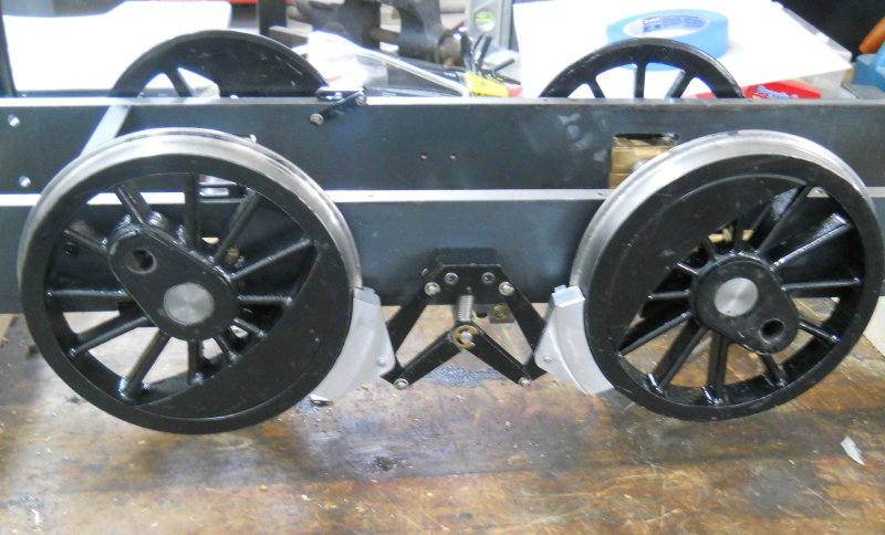 However, when I set the frame upright and pressed down on the brake beam, the wheels and shoes locked up tight and would not release. This seems to be the issue: 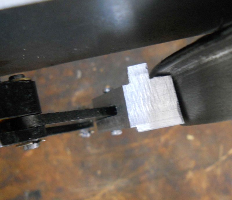 The inner edge of the brake jams into the inner radius of the wheel profile. I think the solution is to reduce mill a larger relief for the wheel flange. The brake surface seems to align very well with the wheel circumference with about 1/8" clearance all around. I'll generate the necessary CNC code tonight and remill the shoes the next time in the shop. Next I CNC milled a radius on the end of the coupler shank and drilled a hole for the pin: 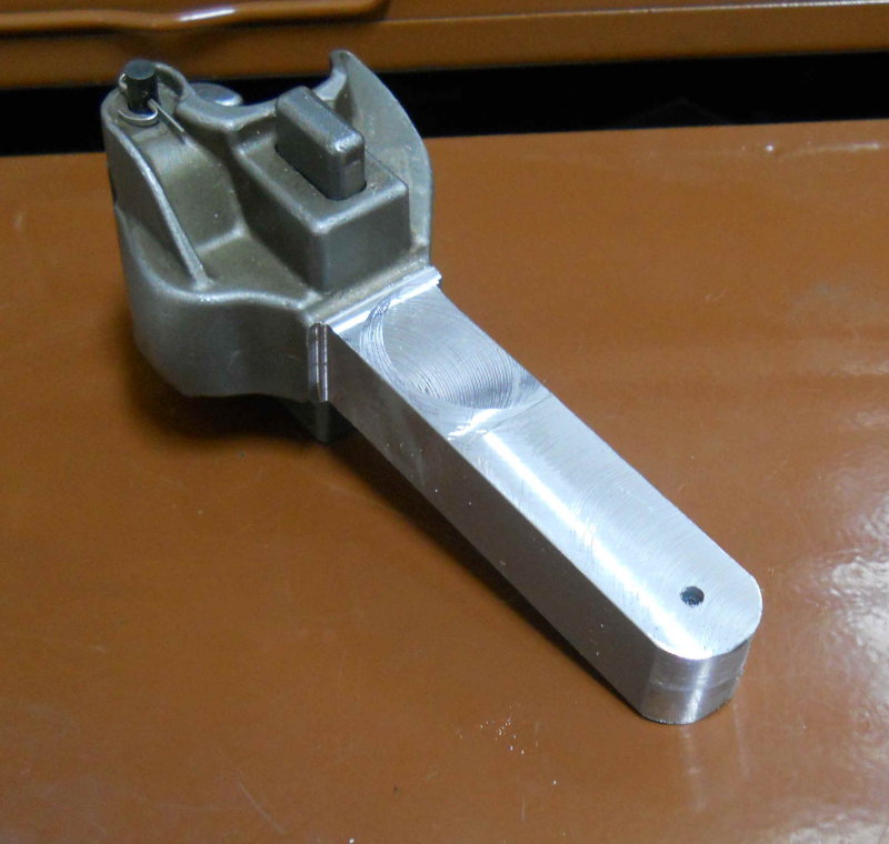 Then a test fit to the frame:  I'm going to hold off on drilling mounting holes for the couple pocket until I verify the coupler height at the track. There's about 20 degrees of side-to-side swing as is, but I may need to narrow the coupler shank to get more angle. |
|
|
|
Post by kvom on Jul 26, 2011 21:17:06 GMT -5
I didn't feel like starting any complicated pieces today, so I decided to finish off the grate supports, one of the first parts I made in this project (back on December 8). I seem to have a habit of making "partial" parts leaving some details to be polished off later. This is probably a bad habit. In any case, I needed to machine pockets on the sides opposite the grate. Despite being simple in theory, I still spent all afternoon. Here are the results:  The two pockets on the right side support are for the latch for the ash pan. Kozo suggests SS, but I just made them from CRS, and will paint.  Of course now I need the 5 pieces that go in those holes, so there's two more unfinished parts. I won't get much shop time the rest of the week as the floors in the house are being refinished, and tracking in swarf is a big no-no. |
|


