|
|
Post by kvom on Jul 27, 2011 15:12:41 GMT -5
Today was the first trial of the chassis on the tracks at my home club in Canton, GA. The assembly performed very well, with no problems on any of the curves or tight portions of the switches or frogs. With such a short wheelbase, the engine could probably handle a 20' radius curve according to one of the members present. Here's a short video taken from the riding car. www.youtube.com/watch?v=M0we2yqJo0MAnd sitting on the tracks afterwards.  The coupler height seems good, so I will drill and tap the buffer beam to mount the coupler pocket, plus shorten the coupler shank. For the next track run I want to have the side rods installed. |
|
|
|
Post by grege on Jul 28, 2011 6:07:53 GMT -5
It's great to see your chassis get on the rails!
|
|
|
|
Post by darian on Jul 28, 2011 8:52:29 GMT -5
Thanks for the inspiration. I should be done with the tender trucks by next week. Also I didn't know there was a Club in Canton Georgia. I don't think to my knowledge there is a club in Alabama.
|
|
|
|
Post by kvom on Jul 28, 2011 17:20:56 GMT -5
After yesterday's trial run, I proceeded to mount the coupler to the front bolster, cut down the coupler shank, and make a coupler pin to replace the screw I had been testing for fit.  Then, based on advice from an experienced builder in the club, I wanted to replace the retaining pin used to keep the side rods on the front crank pin. Kozo's design has a e-clip in a hollow at the back of the driver where it would be inaccessible after assembly. After trying a few things, I finished by using a brass washer held in place with a flat head screw; I countersunk both the crank pin and washer to get the screw head flat to the washer. A trial eyeball fit indicates that there won't be any interference with the conrod.  Despite appearances, the washer does not contact the side rod. |
|
|
|
Post by kvom on Jul 29, 2011 16:55:09 GMT -5
This was my last day in the shop for a while. I decided to finish the parts for the ash pan latch that I started earlier. Needed to make some smallish pieces but all was for the best. These are really finicky in 3/4 scale I imagine. Here's a trial fit photo:  I still need to silver solder all the bits together. The spring is the same as the return spring for the brakes, and is nice and firm. They came in a pack of 3, which was handy. |
|
|
|
Post by kvom on Aug 3, 2011 21:25:35 GMT -5
Over the past two days I've been working on the tie plate, a part that mounts to the frames and provides support for the yokes that in turn support the valve gear. The initial machining was manual, with only the final radius cut (needed to clear the boiler) done on the CNC mill. For this operation, the aluminum fixture plate was drilled to match the mounting holes in the tie plate, plus two additional to retain the scrap part. Here's the assembly at the conclusion of the final op:  The two "feet" are screwed into the bottom notches to allow mounting to the frame, and then the two yokes can be trial fit.  There is a bit of interference between the bottom of the yoke and the driver flange needing to be relieved:  Kozo shows a small angled notch for this on the 3/4 scale, but I wasn't sure it would be needed at 1.5. I also went out to the RR this afternoon with the chassis to test it out with the side rods attached. Here's a couple of short videos: |
|
|
|
Post by kvom on Aug 8, 2011 18:29:07 GMT -5
Today I took 5+ hours to get the first crosshead guide in place. As a novice builder, I struggle with knowing where fit and tolerances are important. But since I've had problems on stationary engines with crosshead guides, I decided to see how tight I could get. Kozo shows soldering the yoke mounts and then machining to fit. I wasn't going to do it that way for several reasons, among which is the problem I had already soldering on the yokes where I couldn't get it hot enough. Also, the yoke was going to be modified from plan because of the width/gauge issues, so I prefer to do a fit "in place." The yokes had 2 1/4" reamed holes for attaching the mounts, so my first task was to machine 4 of these from some 1" round brass stock. The mount body is .75" long, with a 1/4" diameter spigot for attaching to the yokes:  Lots of manual milling later, I have this: 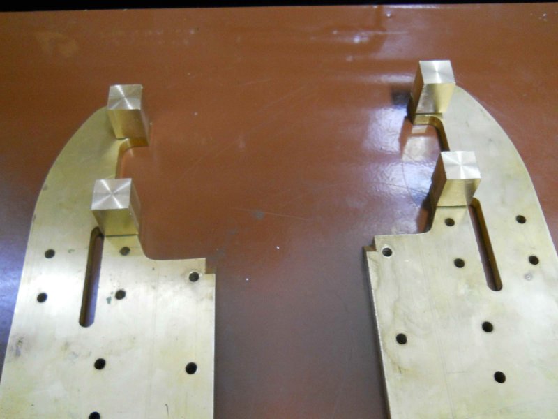 The guides need to be parallel to the frame side as well as the frame bottom. I tried a number of ways to ensure the first parallel to the frame side, but eventually hit on this idea. I knew the distance of the bore centerline from the frame as well as the width of the guide, so I could compute the distance of the inner edge of guide from the frame. I then used gauge blocks to position the bar laterally.  the height gauge gave me the vertical distance at the cylinder end, and also the height of the mount top edge, so now I knew how deep a "notch" to mill in the mount. The final result with the first lower guide in place:  Measurement with a depth mic shows .004" vertical difference between the two ends; I'm satisfied with that result. The upper bar will be a lot easier since I just need to make it parallel with the lower, via a parallel and some gauge blocks to get the needed measurement to make the upper mount. Even though the guides hold the mounts very tightly against the yokes, I'll loctite them in place. |
|
|
|
Post by kvom on Aug 9, 2011 18:08:02 GMT -5
Since I lack material for the rest of the guides (and being burned out on them for the moment), I decided to make a start on the crossheads themselves. With the steel oblong I squared up a few weeks ago, I set up for the CNC mill. I had only .08" at the bottom for clamping with the vise, so was obliged to use soft jaws. Following Kozo's technique of initial machining of both crossheads from the same block, I first did roughing passes to get to here:  After the finishing passes, I had this:  The next step is to turn two round discs to fit into the heads forming a round-end pocket for the end of the conrods. These discs will be silver-soldered, after which the side of crosshead will be cleaned up with a facing pass. I'll have to see if my MAPP torch can heat the assembly enough for soldering. 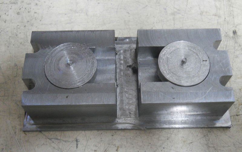 Still lots to do on these afterwards. |
|
|
|
Post by kvom on Aug 14, 2011 20:39:17 GMT -5
This weekend I finished the other 3 crosshead guide bars and their mounts. For now they look pretty good, but we'll see if any adjustments are needed when the crossheads are finished.  I did the measurements with the frame on 123 blocks and surface table assuming that the cylinders are parallel to the bottom of the frame, which was the datum for the cylinder mounting holes. If that proves not to be exactly the case there is some play in the piston rod travel via the packing gland/bushing. |
|
|
|
Post by kvom on Aug 15, 2011 18:06:52 GMT -5
With only a few shop hours available today, I proceeded with the next step in the crossheads. I needed to silver solder the disks forming the pocket for the main rod end, but the MAPP gas torch couldn't produce enough heat. So I used my small Henrob oxy-acetylene torch for the first time. Then I cut the two pieces apart and face-milled both sides. 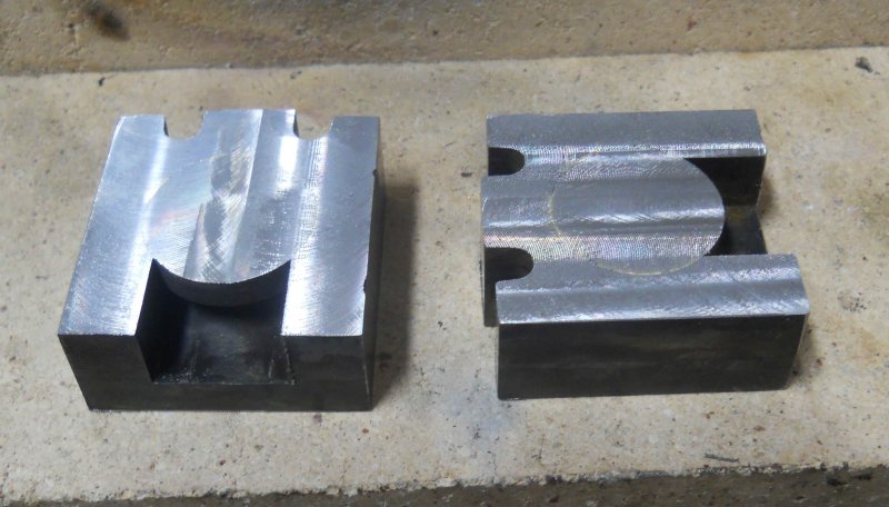 There are still quite a few operations to go on these parts. |
|
|
|
Post by kvom on Aug 16, 2011 18:04:55 GMT -5
Third operation on the crossheads: use the CNC mill to profile the rear face.  Then I used the facemill on the Bridgeport to bring the thickness down to .75" with the pocket centered. |
|
|
|
Post by kvom on Aug 17, 2011 17:52:04 GMT -5
More work on the crossheads including an "O $hit". First task was drilling three lateral holes: 3/16 reamed for the retaining pin, and two 5-40 tapped holes to mount the link bracket. 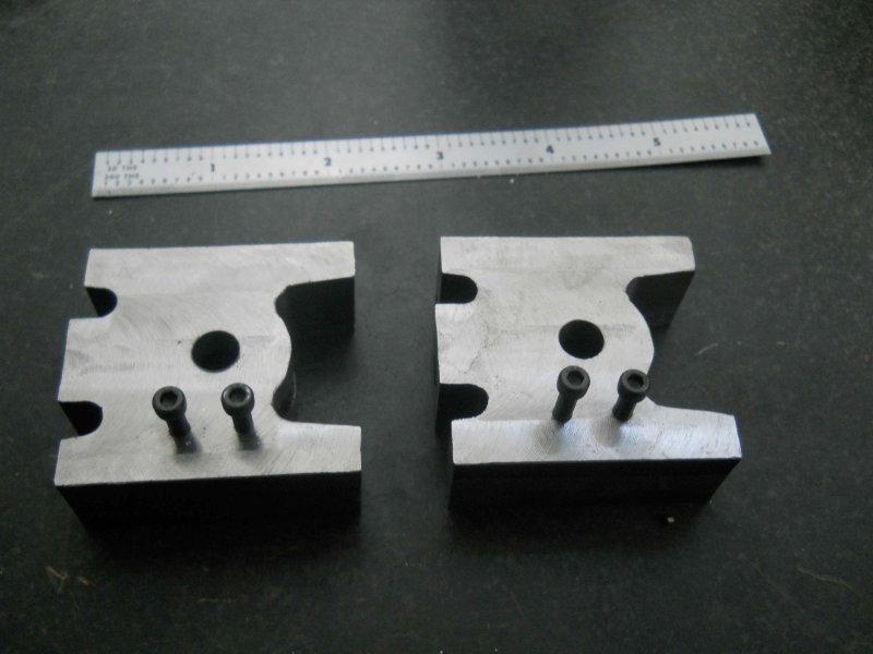 Then I drilled and tapped the front side 5/16-24 for connecting the piston rod, but then discovered that the threads weren't straight. I had started the tap with the mill spindle, but apparently didn't get enough turns to ensure straightness. Plus it was a crappy carbon steel tap (I should know better by now). So I'll order a HSS tap before doing the other. For this one my plan is to bore out the hole to 3/8", then drill and tap some 3/8 rod on the lathe and press it into the crosshead.  I spent the rest of the afternoon making the cross pin that connects the crosshead to the main rod. This simple-looking part took a lot longer than it might appear. The center is drilled 3/16 to accept a Gits ball oiler, tahen 3/32 to 4 cross holes that will allow oil to reach the bronze bushing in the rod end. The threads are 5/16-24, and the inner side of the crosshead will be countersunk to avoid any protrusions that could interfere with the side rod. 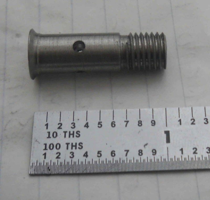  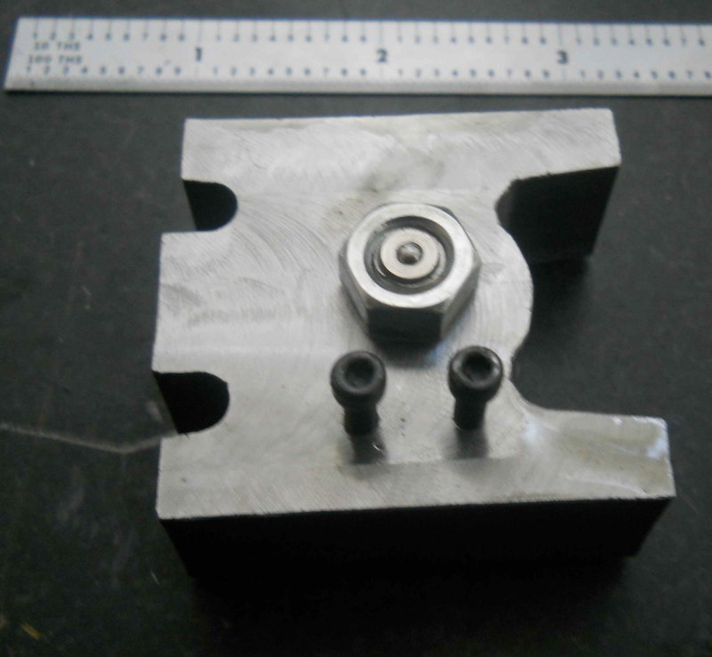 Next shop session I'll try to make the second one come out as good. |
|
|
|
Post by kvom on Aug 19, 2011 15:37:26 GMT -5
Today's plan was to make the link brackets and union links shown on page 104. These are simple CNC profiles, with the holes drilled on the Bridgeport to serve to attach to a aluminum fixture plate. Here's the setup for the link brackets; all holes and screws are 5-40.  A few minutes later: 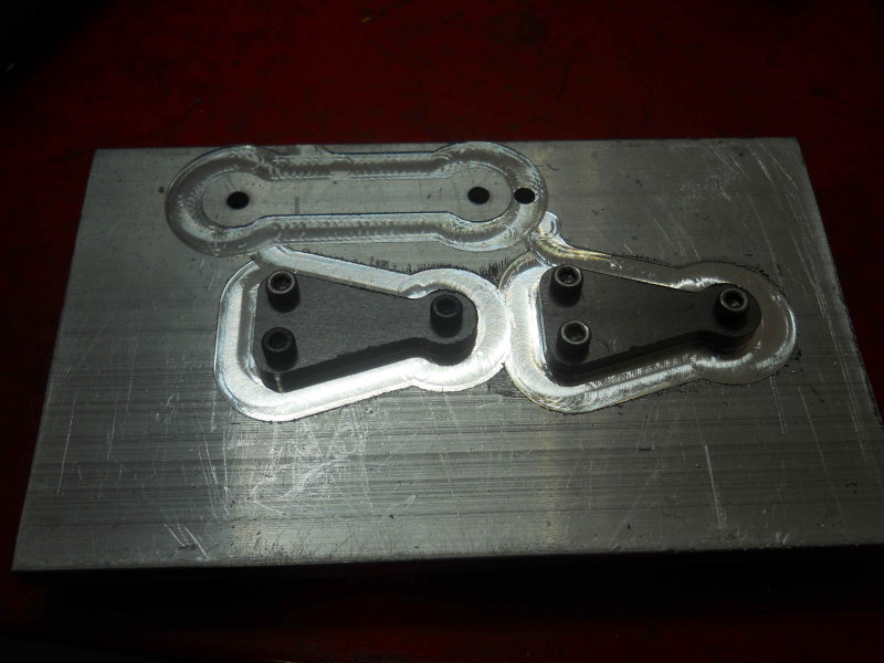 Then it was back to the Bridgeport to enlarge the single hole on each to 5/32. Test fit for to the crossheads, where I discover that the crossheads should be mirrored wrt the brackets, and one set is on the top of the crosshead. grrrr. The union links are shown as well, along with the second crosshead pin that I made yesterday. 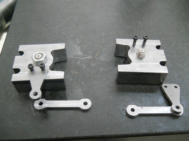 I think the simple fix for the bad holes is to loctite a SS screw in each and mill them flat, then drill and tap new holes in the correct position. My order from McMaster came in just now, so I should have a good 5/16-24 tap to try threading the piston rod attachment properly. |
|
|
|
Post by pkastagehand on Aug 19, 2011 15:56:10 GMT -5
Wow, great progress.
Paul
|
|
|
|
Post by kvom on Aug 21, 2011 17:46:13 GMT -5
Today's project was to finish the combination levers (p. 103, fig 17-9). These had 4 main machining setups. First was to mill lengths of 1/2" square bar CRS down to ~.410" square, drill the 3 holes 5/32", and mill the recess flat where the union link connects. A small aluminum fixture plate is then drilled with matching through holes so that the prepared stock can be attached with 6-32 screws and nuts. The left hole is indexed from the plate's edges so that the machining zero point can be located for the CNC mill.  The second op is then to mill the profile. Here I used a .25" carbide endmill, .125" DOC at 7IPM and 4000 RPM: conservative F&S. 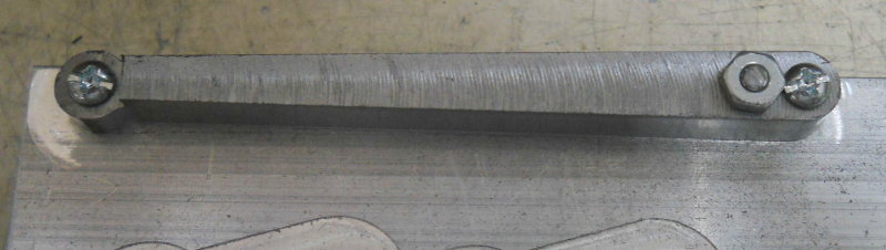 Now the fixture is mounted vertically in the vise, and the "cutout" is machined, again with the .25" carbide endmill. This cutout is needed to clear the main rod.  The final op is to cut the slot where the end of the radius rod lives. Here I used a .125" carbide endmill, .05" DOC, 3IPM, 4000 RPM. 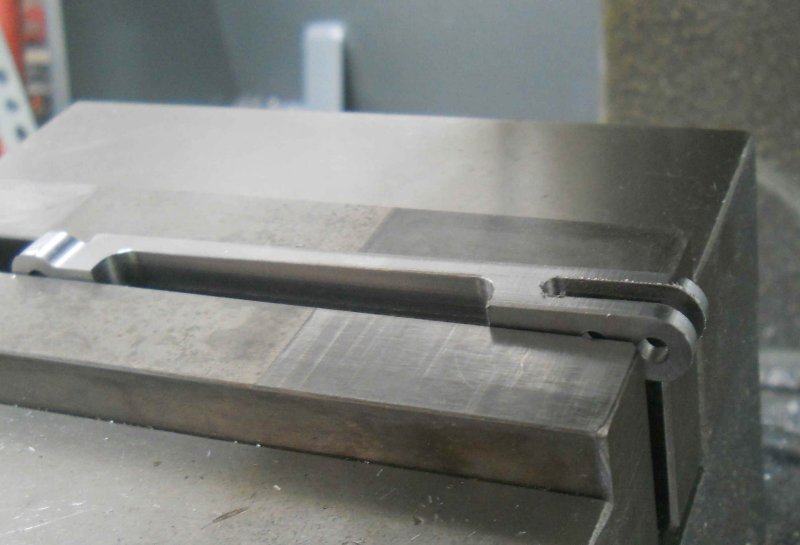 And the final parts:  The radius rods will be done in much the same way, although needing a longer fixture. |
|

