|
|
Post by grege on Apr 22, 2011 7:00:15 GMT -5
Looking good.
I really remember the relief I felt drilling those passages when the first drill broke through in the right place!
The chaski folks probably have more ideas than I do to help your wayward passage- best of luck...
|
|
|
|
Post by kvom on Apr 22, 2011 13:57:41 GMT -5
With some expert advice over at HSM, I managed to finish the admission holes successfully. The main changes I did were using a 26 degree vs. 28 drilling angle, and starting the hole with an endmill as a drill guide. Did successive drilling with 1/8, 5/32, and finally 3/16 using collets vs. a drill chuck. The hole depth is nearly 1.5", so I think some extra drill drift vs. the 3/4 scale could be expected.  So now just a lot of holes to tap. Did I ever mention I hate tapping? |
|
|
|
Post by pkastagehand on Apr 25, 2011 19:13:42 GMT -5
I hear ya; I hate tapping too. I did a number of different things with my A3 (in 3/4") to avoid as much tapping as possible. Welded steel tender frame (clamped in a jig to hold it), clamping parts for silver soldering instead of drilling and tapping, etc.
Some places it might have been easier in the long run to drill and tap for positioning so that shows how much I hate drilling/tapping.
Nice work on the cylinders!
Paul
|
|
|
|
Post by kvom on Apr 26, 2011 16:52:37 GMT -5
Worked on the valves the past couple of times in the shop. I started with two pieces of 1.625" diameter phosphor bronze rod that I faced to final length of 1.32". For scaling Kozo's drawing a minimum diameter of 1.25" would work.  Next, I used a face mill on the Bridgeport to square the pieces to final width and height. Kozo mills andles on all 4 sides to fit the minimum diameter rod, but in this case I could have used the oblongs as is. 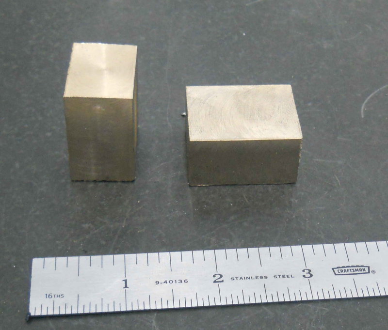 Nevertheless, I proceeded to mill the 45 degree angles on 3 sides. This does leave more volume in the steam chest for steam, so perhaps a good thing.  The valve pocket in the bottom I CNC-milled using a 1/4" endmill. 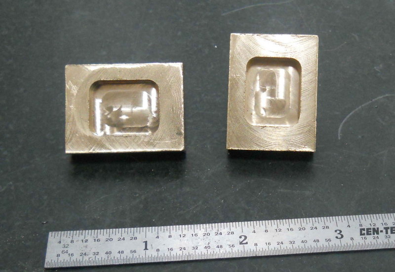 For the lengthwise slot that contains the end of the valve spindle, I notices that Kozo used a 2-56 thread and makes the slot .001 wider than the major diameter. I will use a 10-32 thread (diameter .19) so milled with a 3/16 endmill (.188). The resulting slot is wide enough to hold a 10-32 screw snugly. The cross slot can be any width as long as the nut fits securely. I used a 5/32 endmill and will machine the nut to match.  |
|
|
|
Post by kvom on Apr 28, 2011 21:10:56 GMT -5
Today being "take your son/daughter to work day", my 14 y/0 was working with me in the shop today. Our project was the valve spindle yokes, pg. 103 in Kozo's book. After rough cutting some 1/2" thick CRS on the bandsaw, Melinda was cranking the handles to square the pieces on the Bridgeport.  We then ran the CNC mill to create the profile, as well as center drill for the holes.  Back to the Bridgeport to mill the center gap of the yoke, then drill and ream the through holes:  After drilling the hole to mount the valve spindle, she tapped them 1/4-20.  The finished results, after about 3 hours:  She said she liked running the machines, but all the measuring and setup was a bit tedious. |
|
|
|
Post by kvom on May 17, 2011 13:54:00 GMT -5
Having taken 2 weeks off for NAMES and then some minor surgery, I was eager to get back to work on the A3. The first thing was tapping the 24 8-32 mounting holes for the cylinder heads. This went quicker than I expected as CI taps very nicely. I used the mill/DRO to position the tap vertically and start the first couple of threads, then finished with a tap wrench as usual. I bought a piece of 3.5" brass rod at NAMES that I thought would make up the front cylinder heads. It was about 1.5" long but the ends weren't square. I mounted in the lathe, squared the faces, and then faced the spigots that fit into the cylinder bore on both ends. The resulting piece was now 1.32" long. Now I needed to split this into 2 thin discs. Starting with a 1/16" parting tool, it became obvious that this wasn't going to work, as the tool was flexing. I switched to a 1/8" blade and slowly cut using back gear and ~150rpm. When the diameter was down to 1", I cut the rest with a hacksaw. Here's the result. The rest of the machining will be done on the CNC mill. 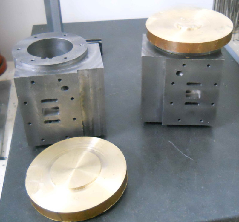 I also bought a piece of 4" diameter brass rod for the rear cylinder covers. I'm hoping it's long enough to part on the bandsaw. I also |
|
|
|
Post by kvom on May 19, 2011 16:09:30 GMT -5
Recovering from surgery, I'm limited in what I can do in the shop (no lifting). So I have a backlog of stuff waiting until I can go full speed. Today I finished tapping all the holes on the cylinders: 8-32 for the steam chest and 10-32 for the tee/frame.
I also got my shipment in from Speedy Metals. A length of CI bar for making the steam chests, and two lengths of SS416 rod for the piston and valve rods, so those are now on the todo list.
I also tried out the 6-7 micrometer I picked up at NAMES for measuring the outer frame width vs. the length of the tee. I have about 3/8 to take off the tee so that it matches the frame. That way the cylinders, frame, and tee all fit together flush on both sides.
|
|
|
|
Post by kvom on May 23, 2011 16:12:16 GMT -5
I was able to trim the tee so that it and the cylinders will fit flush to the outside of the frames. Then it was on to work on the steam chests. While these are relatively simple. I still put in a lot of hours over the past three days. I had a 13" bar of 3.25x1.5 CI, enough for the two steam chests and a third if I screw up. After sawing into thirds and squaring each piece, I had a couple of these. 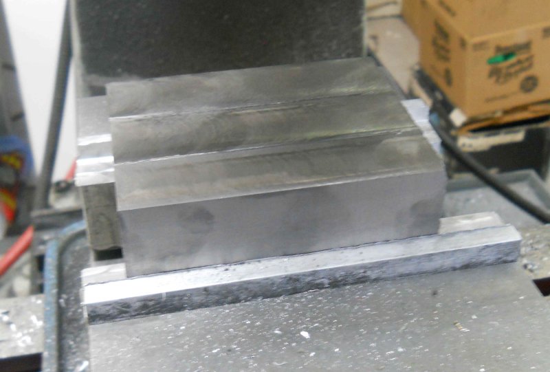 The bars are advertised to finish 1/4" less than the size. Since the chests are 2-3/16" wide, I would not have had much allowance with a 2-1/4 width. However, that meant a lot of CI turned into swarf. Next, used the CNC mill to drill the mounting holes and machine the outer profile. I added two additional holes which will attach to the cylinders but be countersunk and not go through the cover. These will allow the cover to be removed without the steam chest moving. The larger hole in the center is just to allow milling the center pocket with a non-center-cutting endmill. 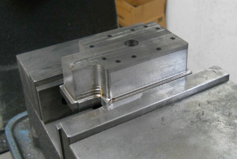 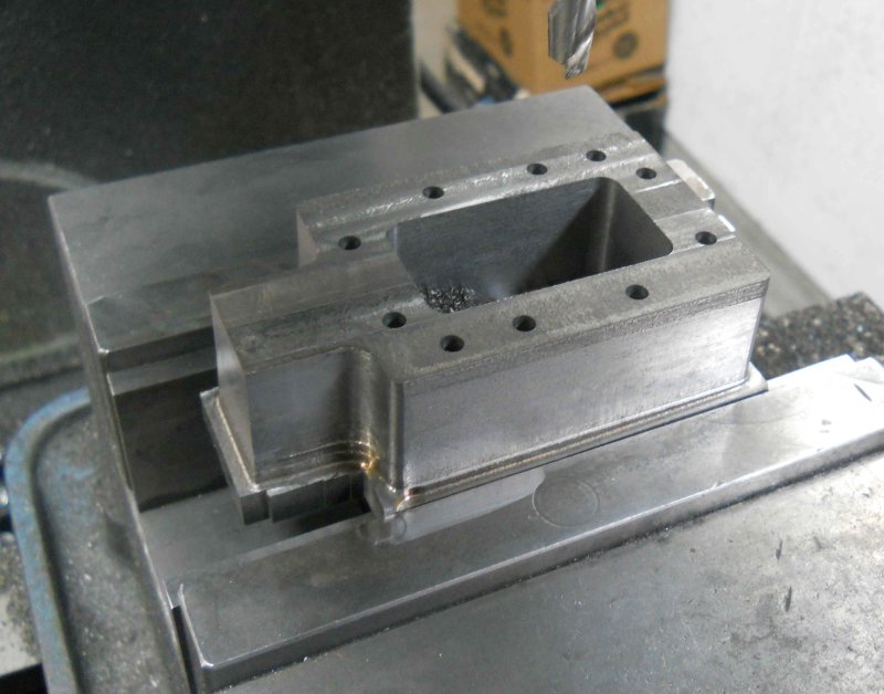 Next the bottom 1/4" is milled off using the bridgeport, leaving the steam chest 1" thick. The slide valve does appear to fit. 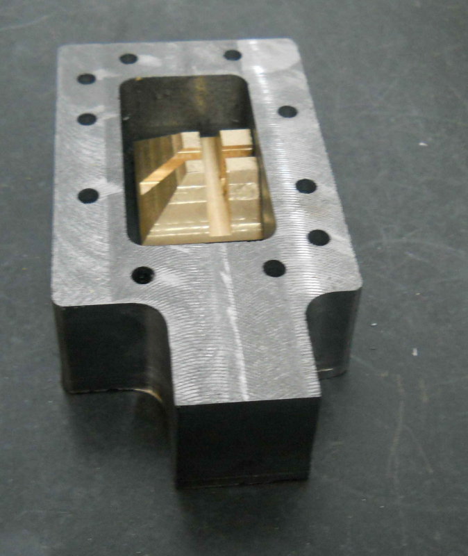 Rather than turn the spigot on the lathe, I used the CNC mill to do it faster. 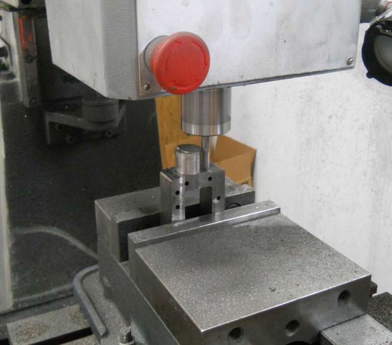 Finally today, put the tee and cylinders together on the frame. I had to trim the ends of the tee a bit as it's a close fit in the frame pocket. 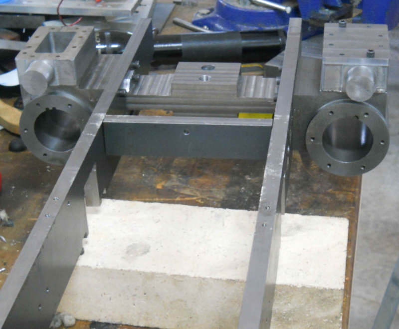 Still to do on the steam chests: 1) Bore a pocket in the spigot for the bushing (yet to be made) and o-ring, then the threaded hole for the bushing retaining screw. 2) Drill the hole for the valve spindle; I will do this with the bushing in place so that all is concentric. 3) Bore the passage in the inner wall to expose the steam admission port in the cylinder. 4) Countersink the two extra mounting holes |
|
|
|
Post by kvom on May 24, 2011 16:33:26 GMT -5
I spent the morning turning the valve spindles (fig 17-6, p. 103). Material is .25" 416 stainless rod. One end is threaded 1/4-20 to match the yokes my daughter helped make, and the other 10-32 matching the width of the slots in the valve. Then it was fairly quick to countersink the two extra holes in the steam chest for 8-32 SHCS, using a 5/16 endmill. Then I started work on the steam chest bore. The design here, as with the piston rod and axle pump plunger, is to seal the spindle with a Viton O-ring and guide the rod with a bronze bushing, which also acts to retain the o-ring within the steam chest spigot. For the valve, the o-ring is a size 2-010. Using Kozo's allowances on the 3/4 scale plan, I computed that the bore for the bushing needs to be .382 in diameter. I happened to have a .380 reamer acquired in an auction lot at a closed shop, so hopefully that will be close enough. So the machine ops for the spigot, after centering on the Bridgeport, were: 1) Through drill a clearance hole. The closest drill I had is an F (.257) 2) Machine a flat hole .432" deep using a .375 endmill 3) Ream with the .380 reamer Here's where I ended the day on the first chest. Once the bushing are made, I will drill/ream the .250" through hole with the bushing in place in the chest. It's not as critical to be concentric since the valve has "wiggle room", but for the piston rod I will need the bushing's hole to be dead nuts with the cylinder bore. I plan to use a similar technique there, 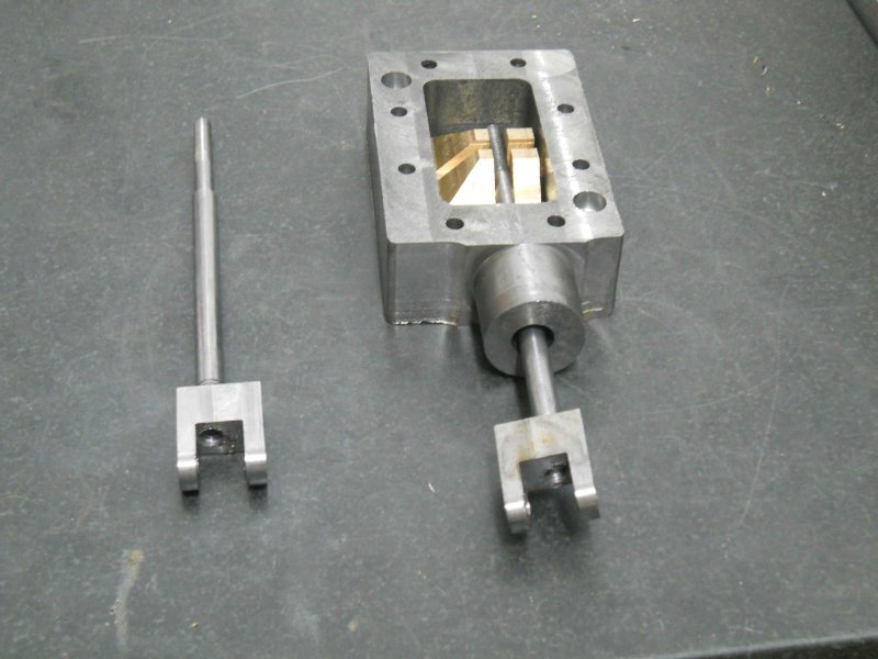 |
|
|
|
Post by kvom on May 25, 2011 16:12:39 GMT -5
Today I just had a few hours after lunch to work, so I finished all the machining remaining on the steam chests, and decided to start on the piston rods. Material is .375" 416 SS, which machines quite nicely. I single pointed the 5/16-24 threads to about 80%, then finished with a die. I still need to drill and ream the cross pin hole and cut the slots on the ends, used for adjusting the piston travel during tuning.  |
|
|
|
Post by kvom on May 29, 2011 9:49:04 GMT -5
The past couple of shop sessions were dedicated to finishing the front cylinder heads. Previously I had turned the mating surfaces and bore spigot from a piece of 3" brass round. To hold these discs, I now needed to make a new set of vise soft jaws. I made two sets from a 6' bar of 1"x2" aluminum ordered from Enco. This bar costs about $11/foot shipped, so for 6" jaws that's $11/pair/ I could have ordered 10 pairs already made from "monsterjaws" on eBay for $113 shipped. The reason I decided to go this route was that I can also make jaws for my 4" vises from the same bar. In any case, it took about 90 minutes to cut, mill, drill, and countersink 4 jaws. These are a bit larger than the standard hard jaws as can be seen here: 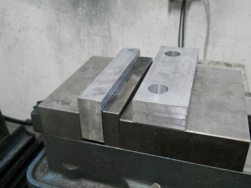 Next I milled a circular pocket in the jaws to hold a piece of round aluminum, then drilled and tapped 8-32 holes to match the pattern for the heads.  Next I milled a 3" pocket in the jaws to hold the heads so that I could face the outer side. 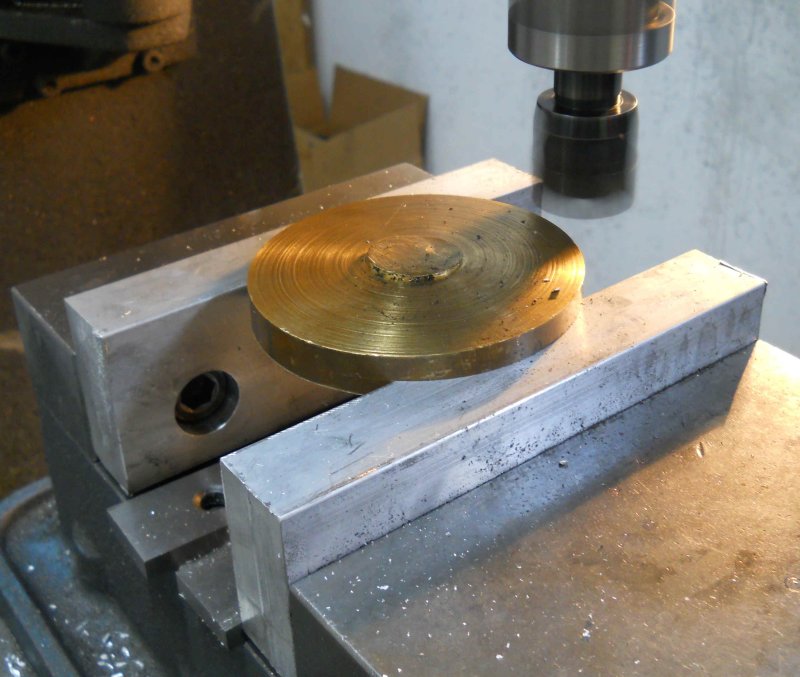 Next, reverse the head in the pocket and use the coax indicator to center on the bore spigot. 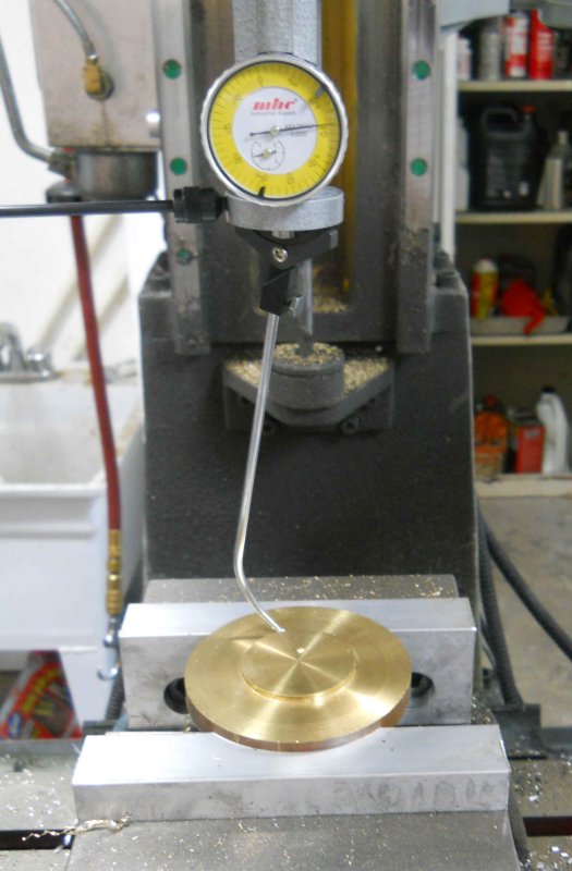 Now I can accurately drill the 8-32 clearance holes centered on the spigot. 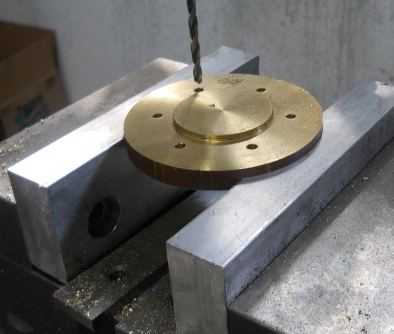 Now the head can be reversed and the outer spigot milled. 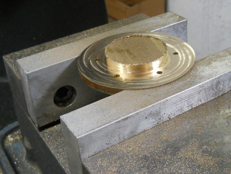 Finally, screw the head to the fixture and mill the outer edge to finish diameter. 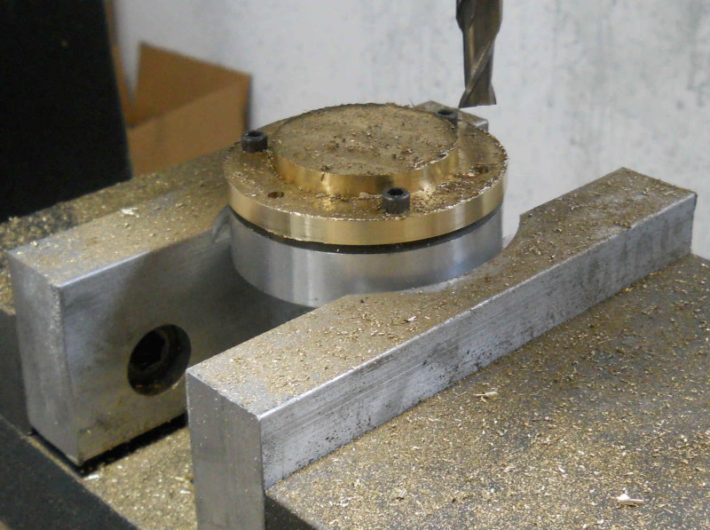 Mounted on the cylinders; like Jesse Banning's versions, I plan to leave the heads exposed and not machine the covers. I have ordered some model-scale hex cap screws to attach the heads, as well as the steam chests. 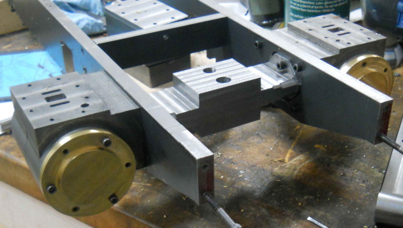 |
|
|
|
Post by kvom on May 29, 2011 17:34:20 GMT -5
For a short shop session today, I made a start on the rear cylinder heads. These start as a 4" diameter drop of brass about 4" long that I bought at NAMES. I tried cutting it in two with the bandsaw, but couldn't get the blade to start straight, so another strategy was needed. After face milling both sides flat, I used the CNC mill to reduce the diameter to 3.5" for a length of 1". This meant that I could chuck it in the lathe. 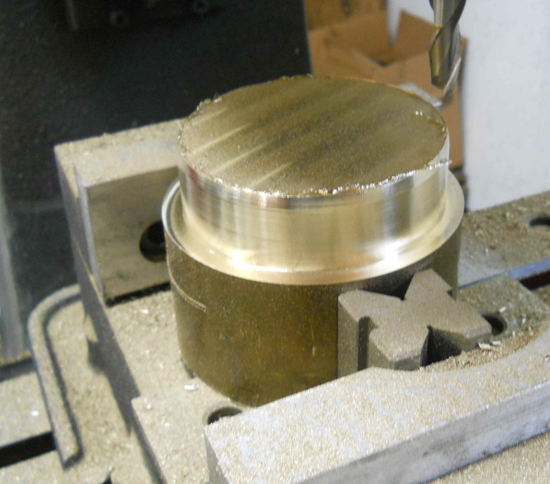 Now I could turn most of the rest down to 3.5", then face and turn the bore spigot for the first cylinder. 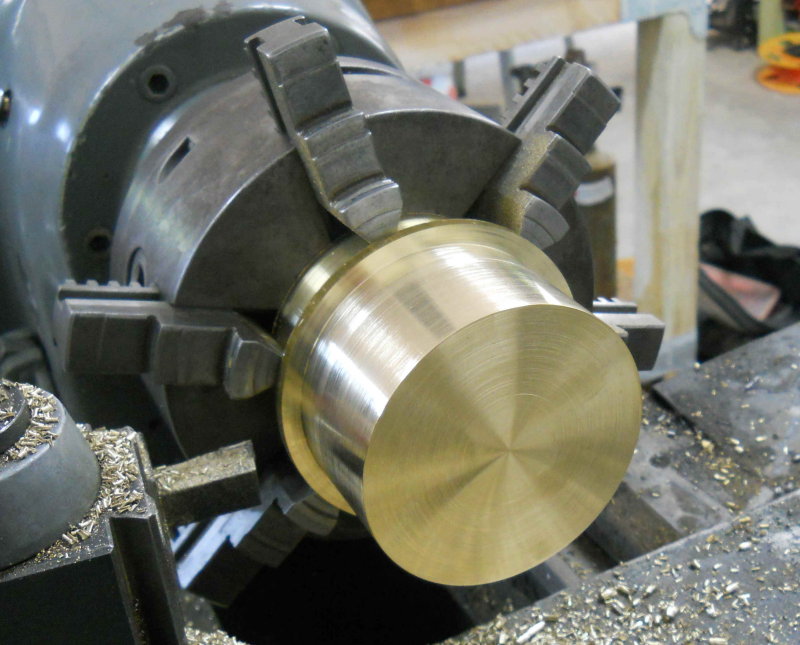 Then I needed to part off the first one. Using a 1/8" parting blade and the lathe in back gear at 200 rpm, I was able to get a pretty good cut. I started out with only 1/2" of blade exposed in the holder, and then successively extended it bit by bit. Once the outer slice started to wobble, I could just break it off by hand. Then I did machined the face and spigot for the second cylinder without needed to rechuck. 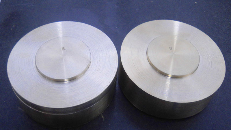 Since these are now 3.5" in diameter, I can use the same pockets in the soft jaws as for the front heads to continue machining. |
|
|
|
Post by kvom on Jun 1, 2011 16:18:44 GMT -5
The next ops on the rear heads were to drill the mounting holes and then mill the final flange diameter. 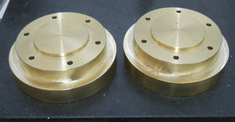 Now I needed new pockets on the soft jaws. 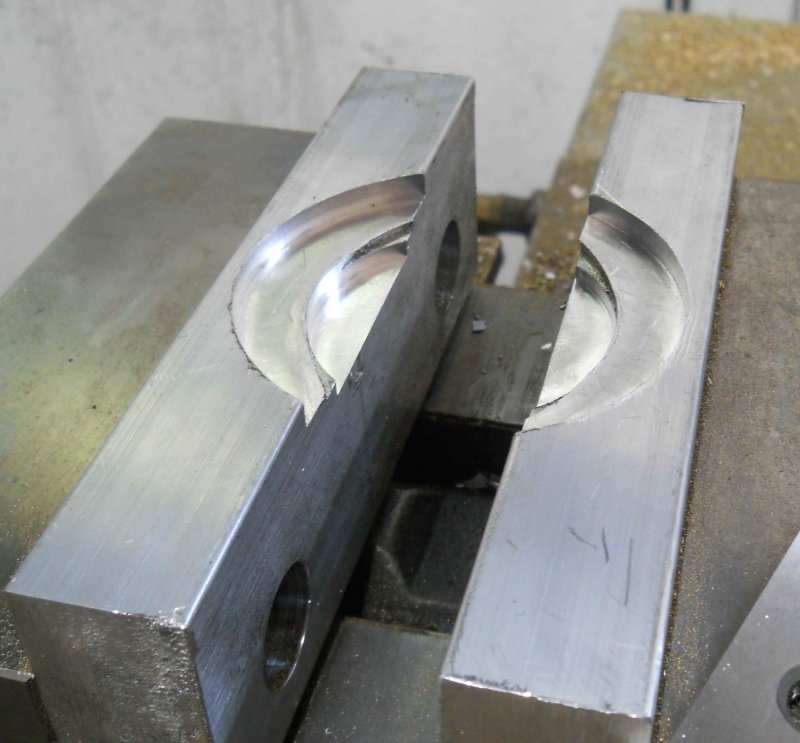 Now the two spigots on the rear side of the head could be milled. 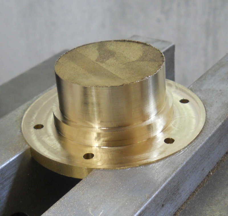 Then the through hole was drilled and reamed .380, and the bushing pocket was milled: .507 diameter, .782 deep using a 3/8 endmill. 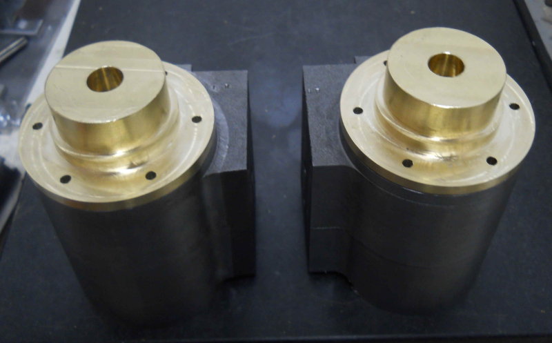 There are still some ops needed on these parts for mounting the crosshead guides, but that will wait until I know the piston will move properly. So the next tasks will be to machine the bushings to fit the pocket, and then make the pistons. I already have the rings, so once it's all together will be the moment of truth. |
|
|
|
Post by kvom on Jun 4, 2011 20:47:13 GMT -5
The past few shop sessions were for making the pistons, parts that seem pretty simple looking at the plans but which took me a lot of time to realize. I started with a piece of 2.5" diameter CI rod left over from a previous project. There was "just" enough there to make the 6 pieces needed for two pistons, so some rechucking at the lathe was necessary. First I turned the diameter down to the 1.745" called for in the plans, then drilled and reamed through. 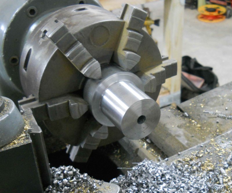 After much difficulty and breaking my 1/16" parting tool twice, I got the pieces roughed out. 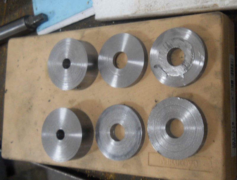 Lots of milling, drilling, reaming, counterboring and tapping later, the result: 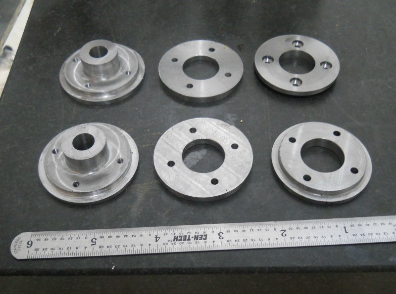 I loctited the large pieces to the piston rods, then assembled using 5-40 screws. Now I could chuck the rod in a collet on the lathe and take a small turning cut to true all the diameters.  Then I turned the bushings from phosphor bronze and did a quick assembly with the cylinders. 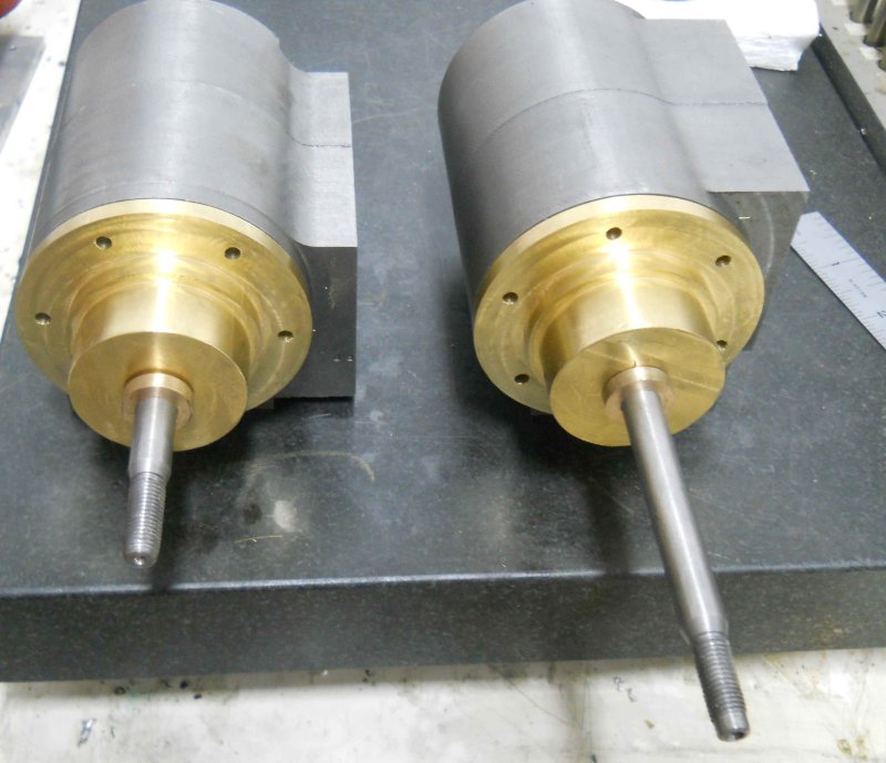 The good news is that both pistons slide smoothly within the cylinder bore, although neither the rings nor the screws for the heads are in place. I have tested that the rings do fit well in the bore. However, the piston body needs enough clearance to account for expansion when running. This is needed since the piston will expand faster than the cylinder when steam is introduced. Kozo's plans call for .005" difference in the piston and bore diameters; based on the design however, I think the clearance can be a bit larger than that without harm. While the green loctite 620 should be sufficient to fix the piston on its rod, I will also add the pin that Kozo specifies for extra security. |
|
|
|
Post by kvom on Jun 7, 2011 16:39:23 GMT -5
Some small but tedious progress today. Using the cylinders as jigs to hold the heads, I milled the flats where the crosshead guides will attach. 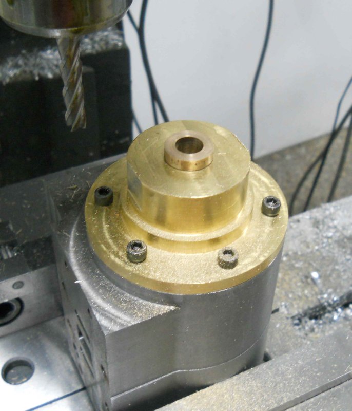 I think this is a better/quicker method than that used by Kozo for the smaller version. Then I drilled and tapped the 5-40 holes for attaching the guides, as well as the hole for the set screw that retains the bushing. 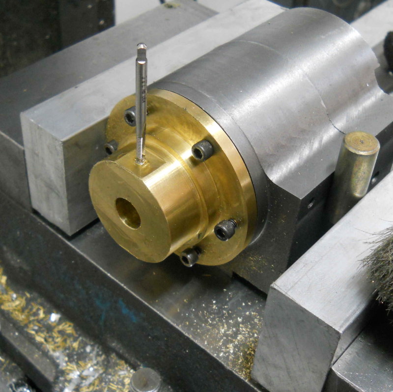 Finally, used a piece of aluminum round to turn the "piston insertion tool" show on fig. 5-8 on pg. 225. This jig has a tapered bore that compresses the rings as the piston is pushed through into the cylinder. It's almost impossible to insert the piston and rings into the cylinder without this (although I tried hard).  Following photo is a test fit of the steam chest/cylinder/cover using the model scale screws from AMS. I plan to leave these exposed and not fabricate the outer covers. The same type of screw will be used for the heads.  |
|

