|
|
Post by kvom on Mar 28, 2011 16:13:08 GMT -5
Thanks for looking in, Mike. The past two shop sessions were spent making the main parts of the yokes. These psrts are attached to a tie plate and in turn the frame. In turn 3 brackets for the valve gear linkage plus the crosshead guides attach to each yoke, and the radius rod passes through the slot. I decided to make these from brass for a couple of reasons. First, I had a 6' length of 4x1/4" 360 brass, and second because some silver soldering is needed and I am more confident in soldering brass than steel. The first operation on the mill was to drill all of the clearance holes for the 8-32 mounting screws. I also cut out one corner on the bandsaw which would otherwise be milled away. The screw holes provide mounts for an aluminum jig plate that I also drilled. 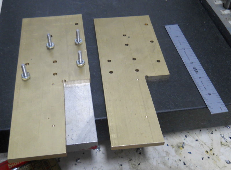 Now the CNC mill carved out the outer profile plus the slot:  After deburring, they're ready for soldering on a bar on the top, providing a support for the walk boards, and two cubes on the bottom that will be the attachment points for the crosshead guides.  |
|
|
|
Post by kvom on Mar 28, 2011 16:35:41 GMT -5
Tie plate calculations
Given that the tie plate, which marries the yokes to each other and the frames, is dependent on the width of the frame, it cannot be scaled 2x Kozo's drawing. The important dimension will be the distance between the rows of yoke mounting holes.
Because the crosshead guides need to be precisely aligned with the centerlines of the cylinders and main rods, calculating the distance depends on whether you build it to match the cylinder or machine the cylinder to match the rods.
Assume that the cylinders are machined to plan so that the centerline of the bore is 1.875" outboard from the frame. The yoke mounting holes are 1.1875" inboard from the centerline. With the frames outer surface being separated by 6-9/16 (6.563), the cylinder centerlines will be 10.3215 apart, making the yoke mounting holes separated by 7.9375".
This calculation should likely be checked against the face-face distance of the rear drivers along with the thicknesses of the side and main rods. Since I haven't made the cylinders yet, I worked back from these figures to get a separation of 7.984, a difference of .0465". Were I to make the tie plate first, I would be obliged to machine the cylinders to precisely match.
Therefore, I have concluded that it's preferable to machine the cylinders first and then tie plate to match, since getting the crosshead guides straight and level is probably one of the more precise fittings required on this build. Once the yokes and crosshead guides are worked out, the spacing of the main rod can be made to fit via the spacer bushing.
I may make a temporary tie plate from aluminum so that I can work on fitting the valve linkage before the cylinders are done.
|
|
|
|
Post by kvom on Apr 3, 2011 8:41:54 GMT -5
After a couple of days devoted to working on the Jeep, I finally got back to the shop to continue on the yokes. The plans call for a 1/4" thick piece to be silver-soldered to the top edge forming a platform to which the walkboards are screwed. Unfortunately, when I tried to SS them, I was not able to get the pieces hot enough for the solder to melt. It seems that the brass just conducts the heat away too fast (I was using MAPP gas torch). So my alternative was to screw the piece to the yoke with 6-32 screws, which will be loctited. Kozo has the top mounting screws tapped into the soldered joint, but with my screw attachment I don't like that idea. So I plan to mill two holes in the joint and loctite drill rod pieces containing threaded holes instead.  On another front, I ordered the cylinder castings from Friend's Models, and they arrived yesterday. 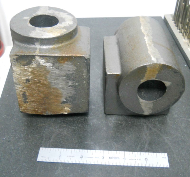 Each chunk of cast iron weighs around 12 pounds! I redrew Kozo's plans in CAD to scale up all the measurements, and it seems that there is plenty of extra material in all dimensions. I've got a decent idea of a machining plan, but want to get it all written down and reviewed before cutting any metal. |
|
|
|
Post by kvom on Apr 5, 2011 18:02:23 GMT -5
Made a start on one of the cylinder castings today. It seems likely that these castings were made originally for a larger engine, as the dimensions are quite "excessive" in every direction. That's not a problem, but there's that much more material to machine away and thus more time. I first machined the steam chest and frame faces flat and square to each other in order for to of the jaws on the lathe chuck to have full contact. I then machined one of the ends flat in order to set square to the face of the chuck. My largest boring bar can only go 4.25" deep, and the casting was about 4.6" in length. So it was necessary to mill both ends down until the length was about 4.1". The final length is 3-7/8, so there's a lot to be removed. Then it was time to mount in the 4-jaw and center on the bore in the casting. It's not necessary to be to super-exact as the cast bore is somewhat irregular and there's lots of material available to adjust to the centerline once bored. I got it aligned to within 1/8" all around. Luckily my chuck has a 2" center hole, so I could bore out to the target 1.75" diameter without worrying about boring into the chuck body. After multiple slow passes I crept up to the target diameter.  The casting is quite unbalanced, so I needed to keep the RPMs down to about 350 to keep the lathe from shaking. Once bored, I turned outer round surface down to it's target diameter, then faced .25" deep to square the sides of the faces. This is an interrupted cut so I took it quite slow.  Once I removed the casting from the chuck, I stamped the face to identify it as the rear. Since it is as close to square to the bore as possible with the lathe, mounting the rear cover and piston opening there will be preferred. That's as far as I got today. There's lots of machining to do on these, so it could take a while. |
|
|
|
Post by kvom on Apr 7, 2011 19:00:31 GMT -5
Today I continued to whittle away at the cylinder casting. First, I machined the front face to bring the piece to the overall final length, then face milled the steam and frame faces down. I left the frame face .025" higher to provide for possible fitment later.  Next I mounted on the CNC mill with the front facing up and used the coax indicator to center on the bore. Then milled to yield this: 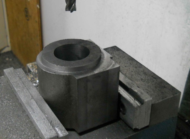 The final work of the day was drilling the mounting holes for the front cover.  I still need to figure how to mill the outer curved profile. Kozo's lathe method would be impractical given the amount of CI still to be removed. |
|
|
|
Post by phutcheson on Apr 8, 2011 1:21:20 GMT -5
Kvom,
See my web site under A3 ... then Cylinders picture #10 and 11.
Although I used a 1/8" end mill you could a much bigger one.
Then use the parting tool.
Pat H.
|
|
|
|
Post by pkastagehand on Apr 8, 2011 11:15:03 GMT -5
I still need to figure how to mill the outer curved profile. Kozo's lathe method would be impractical given the amount of CI still to be removed. I milled down close to finish size holding the cylinder in a mill vise; multiple passes turning the cylinder in the vise between passes. You end up with a faceted curve (a series of flats) but close to finish size. Then you have much less material to remove in the "shaper" process. I think that is what Pat was describing. It goes fairly fast this way since you don't have to be accurate in your rotation between milling passes; all eyeball. Paul |
|
|
|
Post by kvom on Apr 10, 2011 19:09:27 GMT -5
I decided to CNC the outer profile, and up to the end it went well. The first step was a roughing pass leaving .05 " of material for the finish pass. Each pass needs to be done twice (with the profile mirrored) because of the total depth. Here's the end of the first roughing pass: 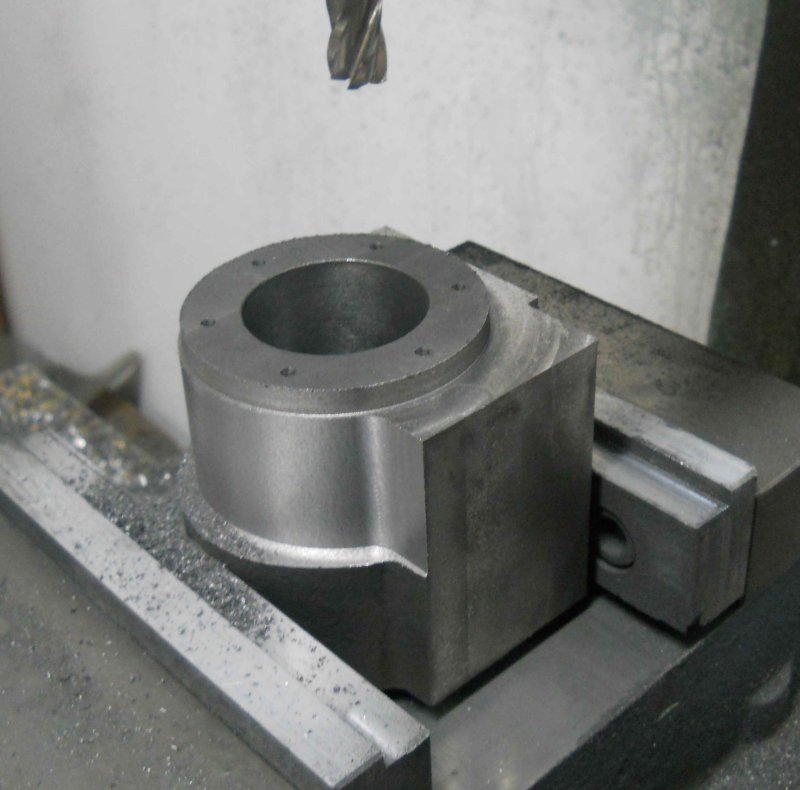 Then the first finish pass: 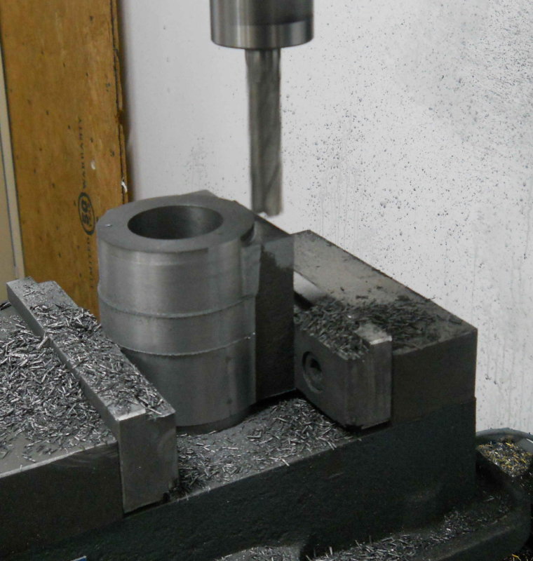 After that the setup was good for drilling the rear cover mouting holes. Then on the final finish pass, the mill decided to have a mind of its own and cut into the face a bit before I could hit the stop.  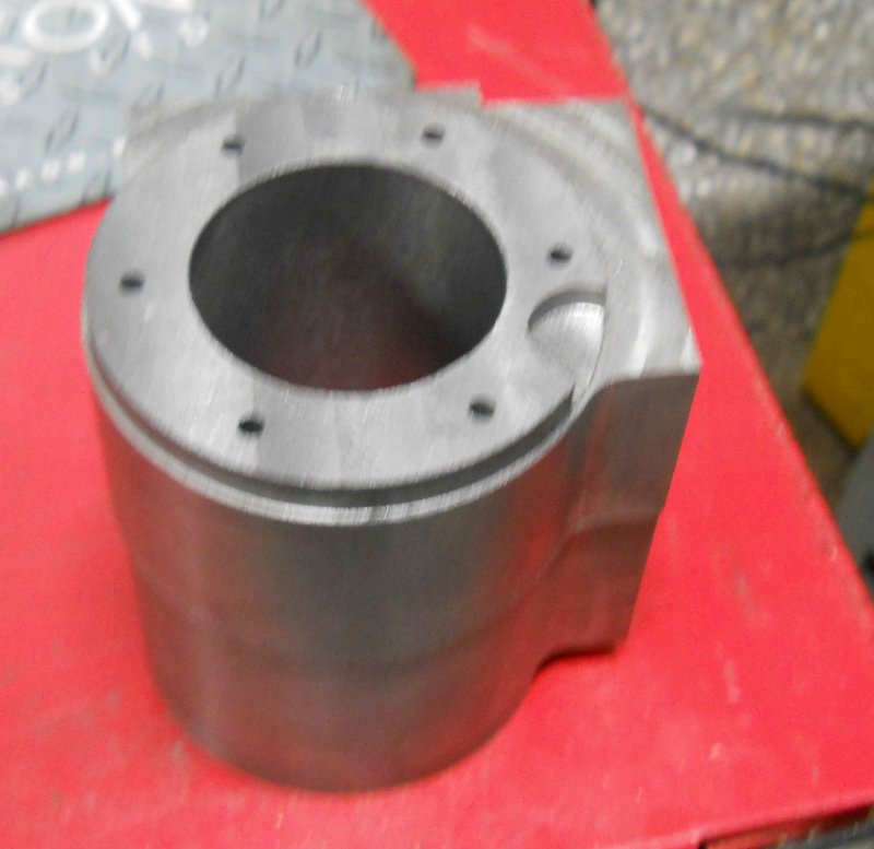 That blemish is not in a critical area and won't be seen with the front cover on as it will be next to the frame, so I'm going to continue on with it rather than throw away a $60 casting and a lot of shop time. Still pi$$ed about it though. Having gone through the steps to this point, I have concluded that for #2 I can CNC the entire profile and save a lot of hand cranking on the Bridgeport. We'll see. And given that possibility, it will be just as easy to machine the cylinder from barstock as from the casting. |
|
|
|
Post by pkastagehand on Apr 11, 2011 15:54:55 GMT -5
As you say it still has a bit of metal for a seal and may not be at all visible cosmetically but if needed something like a little JB Weld may work there. Not sure how it holds up under heat but I've used it on other things and it holds up well. Even used it on an old fuel pump on a car engine once.
Paul
|
|
|
|
Post by kvom on Apr 13, 2011 7:05:40 GMT -5
I weighed the machined cylinder at about 5 pounds, compared with 12 when I started. So there's 7 pounds of CI dust lying about the shop somewhere, and another 7 to go.
|
|
|
|
Post by kvom on Apr 16, 2011 20:51:47 GMT -5
I was out at our local track today and had a discussion with two of the more experienced steam train owners. They said that all the 7.5 gauge locos they know about have blowdown valves on each side, whereas the A3 plans provide for only one on the left. I'm thinking that adding one on the right side would be relatively straightforward.
|
|
|
|
Post by kvom on Apr 19, 2011 12:14:20 GMT -5
Some progress over the past few days since the last post. I bored/turned/milled the left hand cylinder out of its casting, and drilled the holes for the cylinder heads, so it was at the same stage of completion as the right hand. The next stage was drilling the mounting holes on the frame sides. Here my X zero is the center of the bore, the Y zero is midway between the ends. Here's how I set it up: 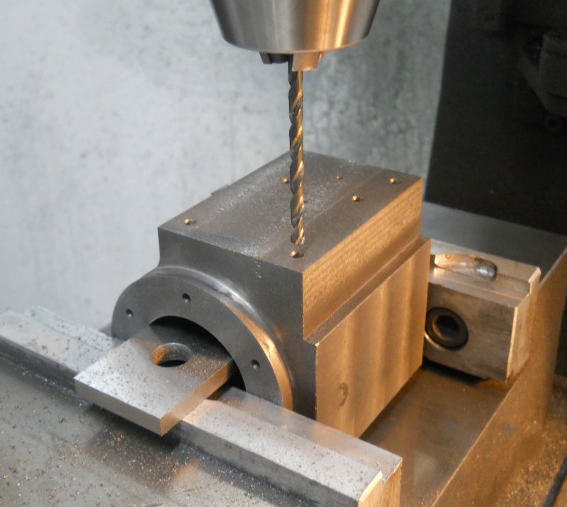 The parallel sits on the top of the vise jaws while the cylinder sits gently on the parallel. A square was used against the steam chest face to square the Z axis. Now an edge finder on either side of the parallel allows the centerline to be found. The hole pattern center is offset from the centerline to the outside, and the tee mounting holes are towards the front. Rather than mirroring the drawing and regenerating the g-code, I used the scale feature of mach3 to mirror the X axis. Thus I could use the same program for both cylinders. That's the first time I've used that feature. The holes for the steam admission and exhaust will be done manually on the Bridgeport. I center drilled to mark the locations.  Now the remaining milling is the steam ports and passages, something that can be a bit nerve-wracking, since a screwup is unlikely to be fixable. I decided to defer that task to a future date. In the meantime, I spent this morning making the steam chest covers on the CNC mill. These would be pretty easy manually, and probably as fast for one, but I wanted to have the rounded corners as Kozo specifies. The first cover tool a couple of hours total getting everything set up and checked out before cutting metal; the second took 30 minutes. I drilled the holes and then milled the profile .26" deep in some .50 CRS, then face milled the bottom on the Bridgeport. The profile was milled .02 oversize. I plan to do a finish pass with the steam chest, cover, and cylinder screwed together so that all have the same. 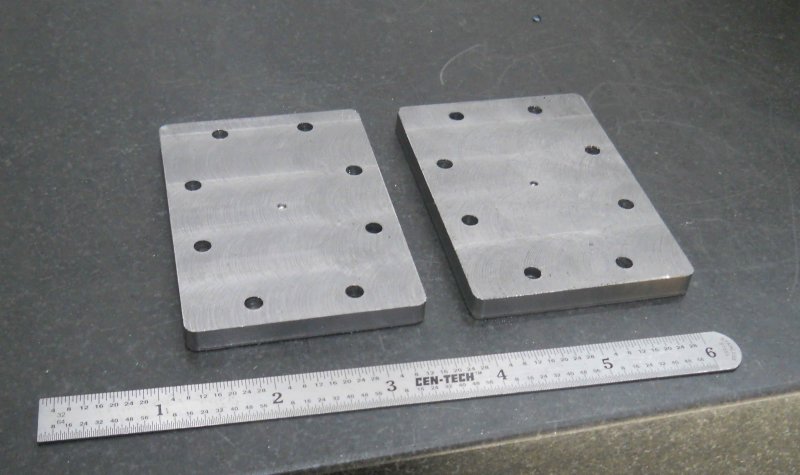 One of our club members suggests an extra pair of mounting holes between the steam chest and the cylinder using countersunk screws. These would allow the cover to be removed without the steam chest itself moving. This sounds like a good idea. I'll wait to finish the cylinders as drawn before figuring out a cood place for these holes. |
|
|
|
Post by kwoodhands on Apr 19, 2011 17:57:54 GMT -5
Adding two extra countersunk holes is a great idea. I wish I had done that myself. If I had done that I think I might have eliminated several hours of work and less cussing.
mike
|
|
|
|
Post by kvom on Apr 20, 2011 21:05:49 GMT -5
Today it was time to drill and mill the steam chest face of the cylinders. In addition to the 8 8-32 holes for attaching the steam chest and cover, I also drilled some holes to clean material out of the steam ports. This way the 1/8" endmill has less work to do.  Setting up, testing, and running took a couple of hours of shop time for the first one. Then the second took just about an hour. 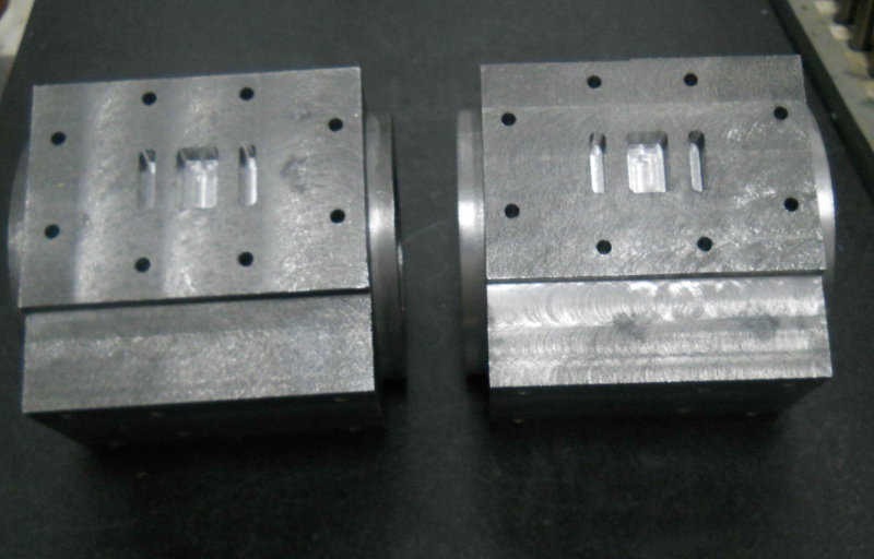 Now just need to drill the passages and tap 26+ holes on each cylinder. |
|
|
|
Post by kvom on Apr 21, 2011 21:00:23 GMT -5
Another session drilling steam passages this morning and afternoon. The exhaust and inlet holes went well, as seen here: 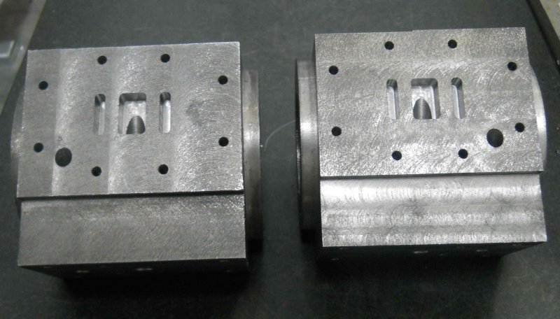 I was a bit nervous drilling at first, but I'd triple checked everything. I was glad to feel the drill bits ending up where they are supposed to. Later this evening I drilled the first pair of steam admission holes. One came out a bit high in the port, so I need to figure out if it can be enlarged any. I drilled these .125 to start, but in theory they should be .196. 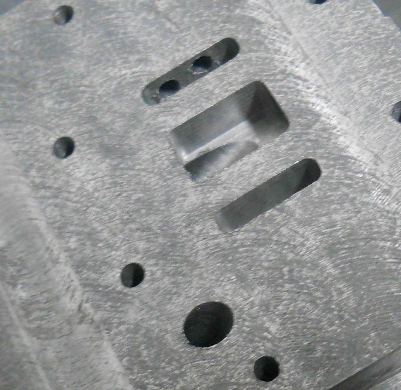 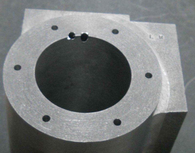 |
|


