|
|
Post by kvom on Mar 1, 2011 18:10:19 GMT -5
Yesterday I finished up drilling the steam and exhaust passages in the Tee. Lots of pecking and chip clearing to get 3.5" deep holes. The steam passage is 9/32 and the exhaust is 11/32. Still to do is take 1/4" off each end; the faces need to end up exactly level with the outside of the frame. Then it's milling the 45 degree angles on the ends to fit through the holes in the frame. 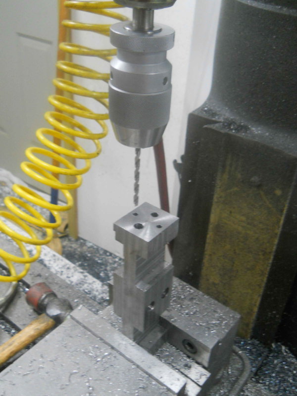 Today I made the second support plate and bracket (made the first some time ago, but ran out of material then). Rather than mill the bracket out of square stock, this time I had some angle iron. That said, it wasn't any quicker to make. 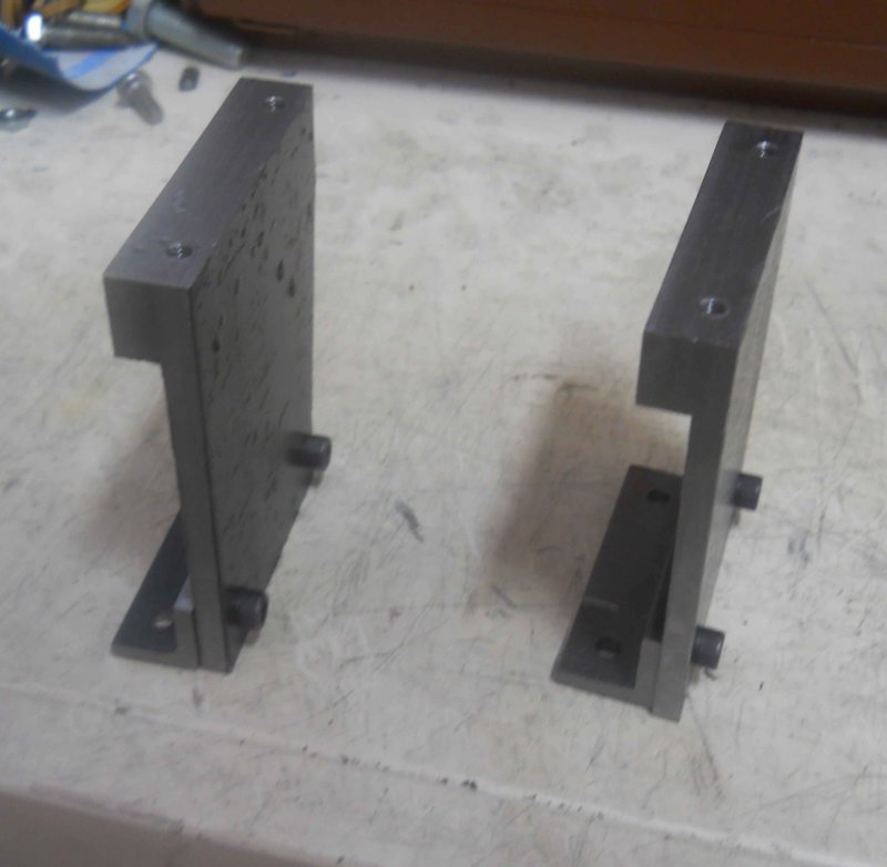 I misread the drawing and drilled the top holes 1/16" too close to the edge, so I'll need to account for that when I drill the running boards. Finally today, I wanted to measure the center to center distance between the two axles, as that will be the distance needed for positioning the bushings in the connecting rods. Not having any accurate hand tools for measuring 12+ inches, I came up with this setup on the mill table. 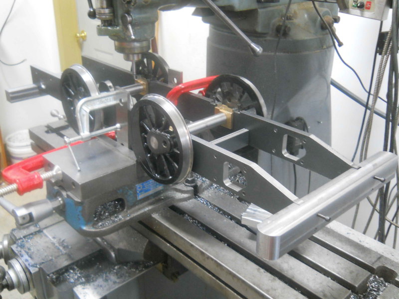 Then I could use an edge finder and DRO to measure. The plans call for 11", and I measured 11.009 in the center and 11.003/.004 at the sides. I am wondering how much slack is permissible here. I assume that a few thousands clearance in the bushings can accommodate movement as the wheels move about. Perhaps experienced builders can comment. I also measured the outside frame widths at front and read. At the front where the tee needs to match, I measured 6.548 vs. 6.562 plan, while at the rear it was 6.525. |
|
|
|
Post by kvom on Mar 8, 2011 7:58:38 GMT -5
With a lot of family todos over the weekend, I haven't made a lot of progress. Yesterday I milled the 45-degree angles on the ends of the tee, so now they fit through the holes in the frames. I had a gouge in one of them when the tool pulled the piece from the vise (too much DOC), but that boo-boo won't be visible.
I also remeasured the frame width at the tee without the wheels and axles mounted and got 5.620, so only .002 off the plan.
|
|
|
|
Post by ramkitty on Mar 9, 2011 16:34:01 GMT -5
how much does the frame weigh at this time?
|
|
|
|
Post by kvom on Mar 9, 2011 19:02:38 GMT -5
how much does the frame weigh at this time? With the wheels and axles mounted, it's getting close to the limit for lifting easily. I'd estimate 60-70 lbs. After a long weekend of family obligations, I got into the shop for a few hours each the past couple of days. Yesterday I decided to make the water pump plunger as it should go quick and I had a length of 1/2" 303SS rod available. The turning went quickly as other than getting the correct length, there were only the bevels on each end. I then used a square collet block to drill the cross pin hole, and then only the slot for the eccentric rod was left to do. My plan was to cut it with the 1/16 slitting saw and then mill to 1/8 width. However, using the 92 RPM in back gear called-for by G-Wizard, the saw stalled without cutting. Adding some RPM was no better. So now I need to try to mill it. Not having much confidence is a 1/8 endmill cutting a deep slot, I decided to first use the hacksaw to make a slit 1/2" deep. This gave a place for swarf to fall. Then I just took .010 deep passes, and widened the slot .01 on each side every .05 of depth. Took quite a while but got there eventually. Then made the exhaust deflector; rather than turning in one piece, I did the shaft and baseplate separately and joined with loctite.  Finally today turned the bronze O-ring retainer/bushing for the water pump. I modified the OD to 3/4 rather than the scaled .772 in order to be able to ream the matching hole in the pump.  Before deciding to finish the retainer, I had started to want to make the crank pins. Before deciding on the OD of the pins, I thought I'd better see what reamers I have to ream the bushings that go over them. Kozo used .281, which scales to .562. The closest reamer I own is 14mm or .551, so that's what they will be. This gives the ID of the bushings, and the OD needs to match the bores in the side and main rods. Kozo used 9mm for the rods, but not having an 18mm reamer my choices are 16mm (.6299) and .750. I drew the main rods in CAD, and .750 will work. If I use .6299 with a .551 ID, then the wall thickness will be only .04, which seems pretty thin. I need to draw the side rods in CAD to see how a .75 bore will work with the other dimensions, |
|
|
|
Post by kvom on Mar 10, 2011 8:00:58 GMT -5
I ran into a bit of a problem when trying to decide sizes for crank pins and their bushings.
The front crankpins have a "retainer" that keeps the side rod aligned. It has a shaft that passes a through hole in the pin and is secured with an e-clip. For this to work there needs to be a hollow milled in the back of the wheels so that the shaft and e-clip don't protrude past the wheel surface where they would foul the axle boxes.
Unfortunately I didn't realize this when maching the wheels, so there is no hollow, and the wheels are already quartered on the axles. So I need to find an alternative way to secure the retainer. My current thought is to thread the end of the shaft and secure it with a nylock nut, meaning that the portion of the crankpin that's inside the wheel will be shorter than the width of the wheel by the height of the nut. An alternative would be a flat nut secured with blue loctite.
Thoughts?
|
|
|
|
Post by phutcheson on Mar 10, 2011 12:07:18 GMT -5
First ... doing a great job on your A3.
If I understand you correctly you are referring to page 75 fig 12-3, the 1/16" cut out (for 3/4) in your case I guess it would be 1/8".
I think I would seriously look into heating one wheel to loosen the Loctite to remove the wheel. Machine the hollow are required, clean and quarter. Don't think you would have to remove both wheels, just one per axle. It looks like you haven't Loctite the Crank Pin yet, so that would be make it easier. Still a pain to do but would bring it back to print and would eliminate unforeseen problems.
Pat H.
|
|
|
|
Post by kvom on Mar 10, 2011 15:30:13 GMT -5
Thanks for looking in Pat.
The retainer is needed only on the front axle, as the side rod is retained on the rear by the main rod. I would need to remove both front wheels to machine for the e-clip, something I'm loathe to do.
I measured the height of a low profile nylock 8-32 nut at .180", so if I just recess the nut into the back of the crank pin bore, I still have .570 of the crank pin inside the wheel. So my plan is to make the pin (fig 12-16 on p.77) with a diameter of .164 (8-32 major) threaded on the end, with the "cap" being .860 diameter by .09 thick. This pin shouldn't get a lot of stress as its purpose is just to keep the side rod end from sliding off (something that ought to be impossible in any case).
I've been advised on Chaski to leave at least .005 clearance between the bushings and the pins, so with the bushing ID reamed to .551, I'll turn the pins to .546.
|
|
|
|
Post by kvom on Mar 10, 2011 20:45:53 GMT -5
After some drawing and calculating, I got in the shop to turn the crank pins. Small dia. is .500 to match the holes in the wheels, and .546 to give clearance for the .551 bushing ID. 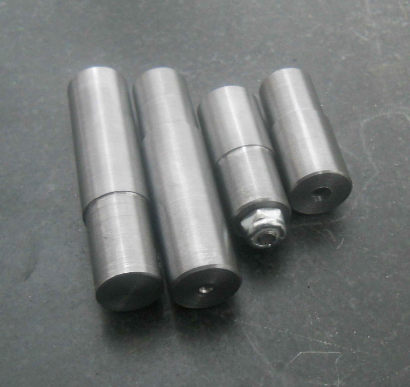 The locknut was to test the clearance of a threaded side rod pin, as I neglected to bore a place in the back of the wheel for an e-clip . |
|
|
|
Post by kvom on Mar 14, 2011 19:33:41 GMT -5
The past few days I've made a start on the side rods. Since my supply of 1/2" CRS is 3" wide, I decided to just make both at the same time from one piece of stock on the CNC mill. So I cut off a piece 13.5" long, squared the edges, and drilled two pairs of reamed .375 holes 11.004" apart. Then I got a piece of donated CRS 2.375" wide; drilled and reamed matching holes. The "locator" pins which pass through the holes keep the stock from moving as it is machined. I made these pins from drill rod. They are a few thou smaller than the combined thicknesses of the jig plate and stock, through drilled 1/4". 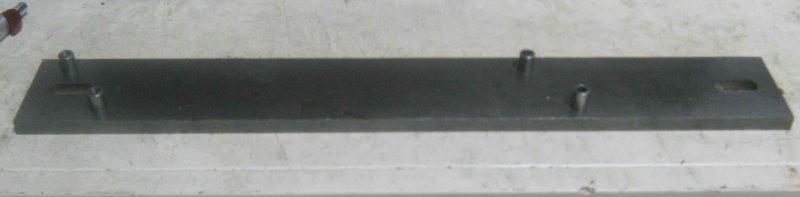 Now I could mate the stock to the jig and secure it with 4 1/4" screws and nylon locknuts (locking nuts are needed as the vibration from milling can loosen normal nuts. 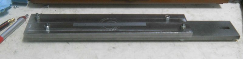 The jig plate is mounted on the CNC milling vises. I like these two 4" vises vs. a 6" vise as I can hold longer pieces.  The first operation was to rough out the shapes using a 3/4" HSS 2-flute endmill. 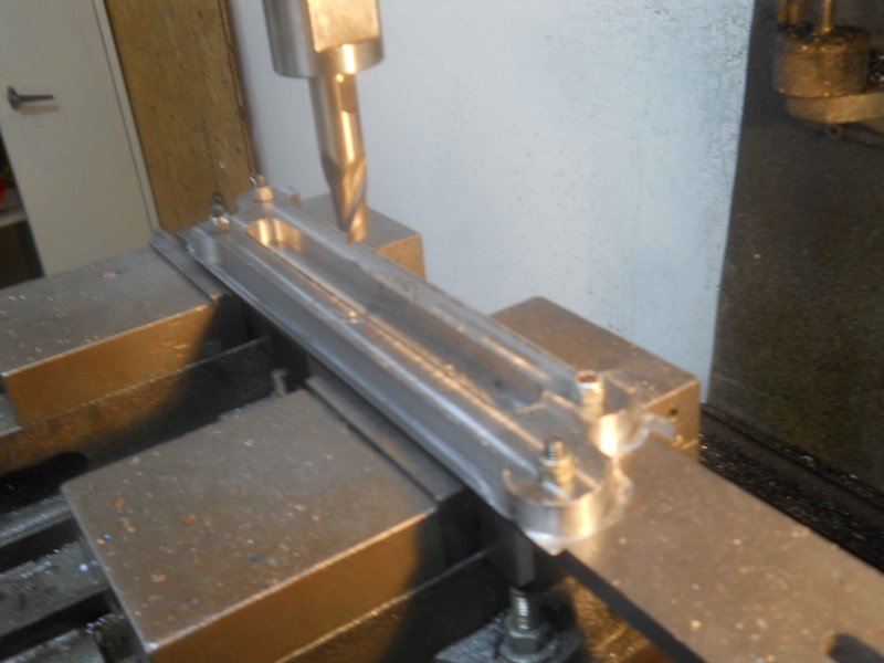 Then two additional passes with a 7/16" carbide 4-flute endmill, and I end up with these: 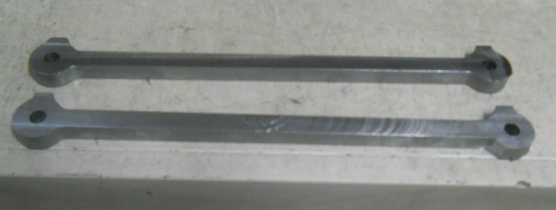 All the rest of the work on these will be manual milling. I learned quite few things doing these pieces, and making the main rods should go a lot faster. One thing that stands out is that I should make each singly from narrower stock. The necessity to rough out the "valley" between the two means a slot cut, and that needs a much slower feed rate. Machining a single from the outside in can be done considerably faster with deeper cuts. Work remaining is to drilling/reaming the holes for the bushing, counterboring one hole in each for the retainer pin, drilling the oiler holes, and narrowing the "neck". The pieces are also .08 too thick, so that will be faced off to spec. |
|
|
|
Post by kvom on Mar 16, 2011 18:01:02 GMT -5
Yesterday and today more work on the side rods. I needed to accurately enlarge the 4 crank pin holes to .75" (i.e., keeping the 11.004 hole center separation). After mounting the ron the vise, the I used a locator pin plus the coaxial centering gadget to center the spindle over the hole. 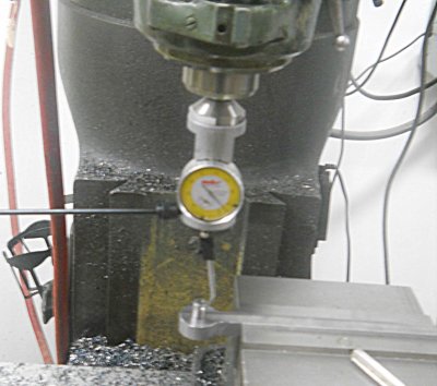 With the table locked, I enlarged the hole by drilling by 1/16ths up to 11/16.  Then a further 1/32 via the boring head (This will correct any wandering of the hole caused by the drills).  Finally the 3/4 reamer.  Repeat 4 times. Then it was on to the lathe to turn phosphor bronze bushings for the rods, plus two for the large end of the main rod. The bushings were reamed to 1/2", and will be enlarged to fit the crank pins once they have been loctited to the rods. For now it's just a push fit. 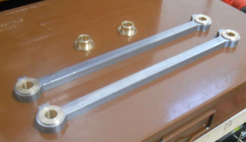 |
|
|
|
Post by kvom on Mar 17, 2011 18:06:07 GMT -5
Today I finished profiling the sides of the side rods and loctited the bushings. Rather than the side flutes of a 1/4" endmill for the radii, I used the end of a 1/4" ball mill. This saved making the jig that Kozo suggests. 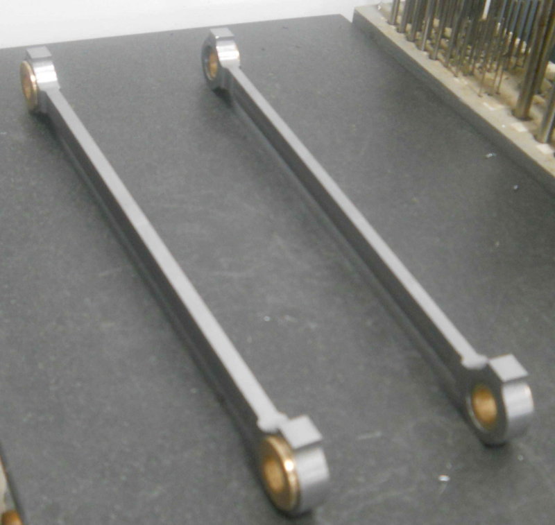 Next I'll ream/bore the bushings and finally see if how they work mounted to the drivers. Still to do is drilling and tapping for oil cups on the ends. That's wait on a make/buy decision on the oil cups. |
|
|
|
Post by kvom on Mar 18, 2011 17:05:31 GMT -5
A "milestone" today. I finished drilling/reaming the side rod bushings and mounted the rods and crank pins onto the drivers. No binding, smooth as silk. So the measurements and quartering look good. That's a load off.  I plan to do the main rods and reverse cranks next, so that I can trim the crank pins to length. I'll also be able then to measure the centerline separationof the main rods, and move on to the cylinders. The crank pins are in the wrong drivers in the photo, but they are just for fit (not glued in). |
|
|
|
Post by kvom on Mar 20, 2011 15:22:43 GMT -5
Yesterday I started on the return crank, a part that attaches to the rear crankpin and along with the motion of the crosshead creates the timing for the valve. After cutting and squaring pieces of 1.5x.5' steel and drilling the two holes, I mounted them in the CNC mill vise to mill the outer profile.  I used soft jaws here as I was milling quite close (leaving .10) and hate to mill my hard jaws. I also wanted to use the soft jaws for the last step. Now to the Bridgeport to mill the relief (needed to clear an e-clip for the attached part). The radius cut was done with a 1/4" ball end mill, taking lots of small cuts.  Next, I milled the clamping slots using a 1/8" endmill on the Bridgeport, taking only .015 DOC each pass and blowing chips with air all the while. Tedious, but the endmill survived. Per plan, the slot would be 1/16 but it doesn't matter in this case.  Next, I drilled and tapped the clamp screws using 8-32x1"  Now it remained only to remove the square backing that remains. Since the part is not suitable for regular cvise clamping, I milled a pocket in the CNC vise's softjaws, enabling the parts to be held securely. Then used the facemill. 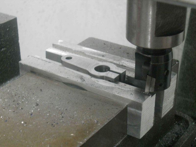 Mounted on the crank pin for a poser shot: 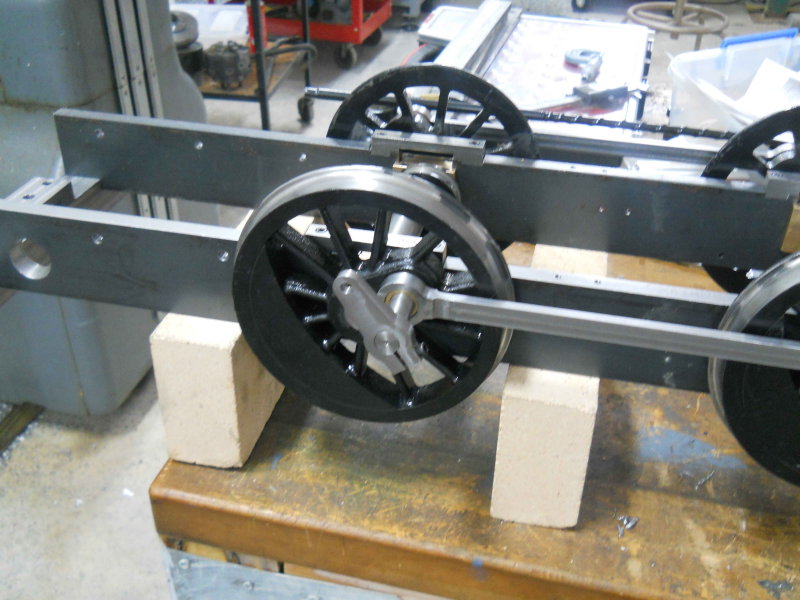 |
|
|
|
Post by kvom on Mar 24, 2011 15:29:05 GMT -5
The past three days were spent making the main rods, with shop time interspersed with real life. I had cut and faced the 1/2" CRS stock a while back, so the first tasks were to drill mounting holes in both the stock pieces and the jig plate, similar to the side rods. Then it was on to the CNC mill to make the outer profile. 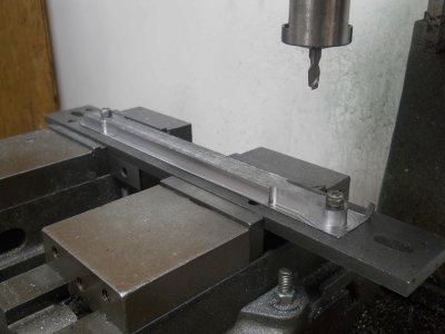 Then it manual milling for all the rest. First, face mill to remove the bottom remainder.  I diverged from the plans a bit, as Kozo's dimensions result in a 1.4 degree included angle between the top and bottom of the shafts. Since I was going to use angle bars to finish the angles and have only integer angles, I redrew it to give a 2 degree shaft taper. In order to be able to mount the shafts in the milling vise, the CNC profile has the taper on both ends and leaves it square in the center. The next operation was to drill/bore/ream the bearing holes, .75" and .5". 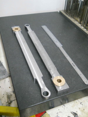 The next operation was to mill the shaft to a .25" thickness.  Next mill the side radii using a 1/4" ball end mill. 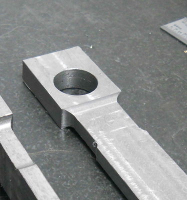 Next finish the first taper using a 1 degree angle bar for setup. 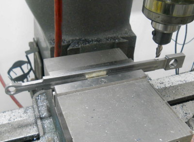 For the opposite side I needed a 2 degree bar. 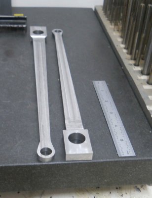 Poser shot: 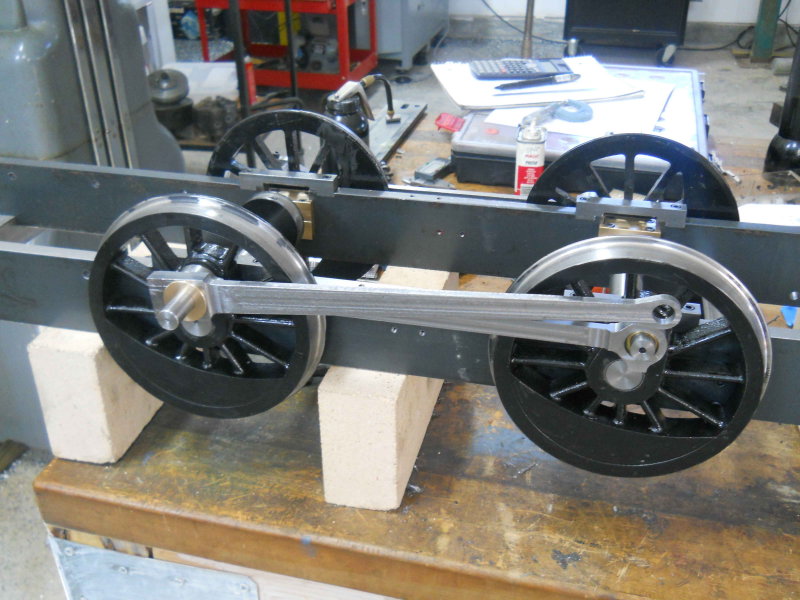 |
|
|
|
Post by Harlock on Mar 24, 2011 18:45:01 GMT -5
Congrats on the square rod setup - no binding! A great achievement.
Looking great. I hope to one day get back to my 3/4" A3.
-Mike
|
|


