|
|
Post by ramkitty on Jan 13, 2011 11:54:54 GMT -5
It is amazing how fast this goes with cad,cam and a cnc machine.
|
|
|
|
Post by kvom on Jan 16, 2011 19:07:12 GMT -5
Having been given some 1/8" thick CRS, I determined to make the spring hangers. There are 14 in all of 4 different varieties, including 8 with slots. My goal for today was to make the 6 that lack slots, pending arrival of my delayed Enco shipment with new 1/8" endmills. Having some 1" wide strip, I cut off 10". To accomodate this on the CNC mill, I milled "parallels" into the soft jaws on both 4" vises; since these were done in a single pass, the vises are automatically trammed to each other. I also don't have to worry about the tools cutting through and striking metal parallels. 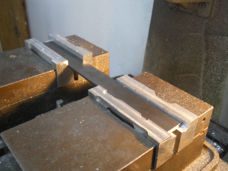 One of the 6 didn't work out well, but I did end up with 5 usable hangers. The 6th will be made in the same run as the other 8. 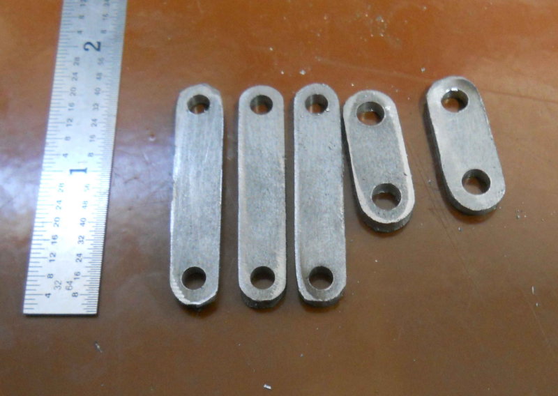 The other task of the day was to drill and tap the mounting holes for the brake lever brackets on the bottom of the side frames. 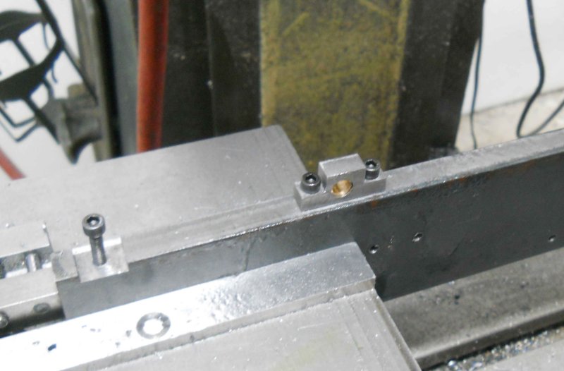 |
|
|
|
Post by kvom on Jan 17, 2011 12:57:24 GMT -5
Spent a while in the shop this morning making the drawbar pocket and drilling/tapping the foot plate to mount it.  |
|
|
|
Post by kvom on Jan 25, 2011 17:26:56 GMT -5
I made some progress the past few days, although not without pain. I was milling the support plate (p112) that attaches the foot board to the running board and broke an endmill from a too-aggressive cut. The piece was also ruined. I went ahead and finished one, but will need to find another suitable piece of steel to remake the other. FWIW, I milled the two pieces as one to avoid the need to SS the two pieces together. Yesterday I spent the entire afternoon in the shop of a fellow club member and constructor, shooting the breeze and absorbing a lot of RR and knowledge (hopefully some will stick). I had brought over the coil of spring steel, and my friend used his shear to cut all of the pieces for the spring packs to length. Today I used a 1/8" 4-flute carbide endmill (fresh from Enco) to drill out the center holes in each leaf. I cut the slots in the ends of the top leaves by drilling 3 adjacent holes, then milled them together. Just need to finish the hangers to get the suspension machining finished.  |
|
|
|
Post by kvom on Jan 28, 2011 16:26:54 GMT -5
Yesterday I spent machining the two axles. These are just two steel cylinders .874" in diameter and ~8.625" long. My raw material is some nice steel rods that were donated to school and free to me. They are 3' long and 1.25" diameter. My lathe is just an inch or two too short to try to turn both axles together, so it went one at a time. I noticed problem while turning to diameter, in that there was a taper of about .002-3" over 6", with the diameter getting smaller towards the chuck. So I decided to turn to .880, finish the end near the tailstock, then part off and turn the other end plus the center with the piece chucked in a .875 collet. Theory did not meet with practice; while I measured the diameter at .874, once I fit the axles to the wheels it was obvious that the fit was quite loose. A new measurement showed the end diameter to be .007 too small. Since I plan to fix the drivers to the axles with 620 Loctite, that gap is not a problem. However, it's enough difference to allow the axle to wiggle a bit, meaning that the two drivers might end up not perfectly parallel to each other. My theory on this relates to the fact that the steel was very hot when removed from the lathe. I believe that it expanded during turning; and since the more massive chuck acts as a heat sink, the end nearer to the chuck stays cooler, hence has a smaller diameter. So I think I'll remake these, first turning to .885, then letting them cool down before finishing to .874 or a sliding fit on the drivers. Since this type of machining is a bit tedious, I decided to spend today making the eccentric that mounts on the rear axle and drives the water pump. This is made from grey cast iron. The disc is 2.063" in diameter, .625" thick, with the slot for the strap being ,44" wide and a diameter of 1.872. I had a piece of 2.5" diameter CI rod left over from another model build, so it went onto the lathe. Turning and facing were no problem. However, I had a lot of chatter cutting the perimeter groove with a 1/8" wide parting tool. I think the problem was that the piece stuck out too far from the lathe jaws. In any case, I put the lathe in back gear and went in super slow. Then cut off with the bandsaw. Next, I chucked the disc in the milling vise to mill to thickness and remove the saw cut marks. The interior hole matches the axle diameter and is offset .400", giving a stroke of .800 inches to the pump piston. I drilled out to 13/16 with a succession of drills, bored a further .06, and finished by reaming .875. The final step was drilling and tapping for a set screw. The 3-3/4 scale engine uses a 5-40; Kozo doesn't give much indication about fastener sizes, so I decided to go with 8-32. The hole from the far side of the axle bore is over 1" deep, and too long for my 8-32 tap to thread through completely. I decided to counterbore the hole for an 8-32 SHCS, but even using a normal set screw it makes sense to counterbore the hole before tapping. With the counterbore, a 1" SHCS fits perfectly. Once the water pump is built and everything is lined up, I'll put a dimple on the axle under the screw to ensure that the disc won't ever slip.  |
|
|
|
Post by kvom on Jan 30, 2011 18:47:56 GMT -5
A most "axle-ent" day in the shop as I succeeded in machining the axles to a good slip fit on the drivers. Starting with the 1.25" stock in the 6-jaw chuck, I turned down to the largest 5C collet (1.125), and from there on I was able to use the collet chuck, which is more accurate. l alternated the axles until both had been reduced to 15/16, at which time I broke for lunch and allowed the steel to return to ambient temperature. From there I turned down just 2" from each end to the target diameter of .874. Once I had the first end that had a good fit to the driver bore, I didn't change that measurement on the DRO and turned the other three ends. By taking short, shallow cuts the metal doesn't heat up and expand as it did previously. While the resultant diameter fit the drivers very well, they were a tight fit to the axle box bores, but by loosening the screws slightly that hold the two halves together I could rotate the axles in the boxes. The eccentric disc didn't fit well at all, and I ended up boring it out and additional .01. Once all that was done, I couldn't resist doing a test assembly. 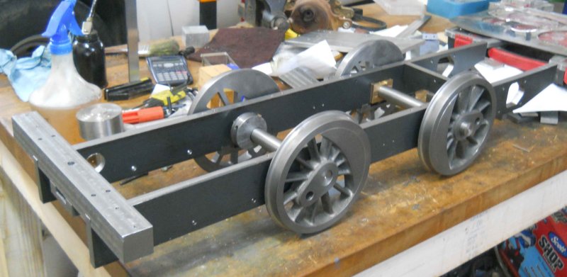 It looks as if I have .10" of sideplay on one axle and .07" on the other. I need to shorter the axles to their final length and paint the drivers, and then I can think about quartering. I was happy to see that the axles turn without too much effort when it's all together. |
|
|
|
Post by kvom on Feb 4, 2011 14:55:22 GMT -5
I ordered paint and prep (POR15, degreaser, etcher, top coat) for painting the drivers prior to quartering. That should arrive Monday. In the meantime I decided to skip a page and mill some aluminum, taking a break from the steel. Having scored a block of 3x3" 6061 from the school scrap bin, I started on the headlight. After making quite a lot of chips, I had the basic oblong stock milled to dimension.  The rest was just cutting out the chimmney and the angles. My CAD program calculated the angles to several decimal places, but as I have only integer angle blocks I just rounded up. It still came out pretty decent. 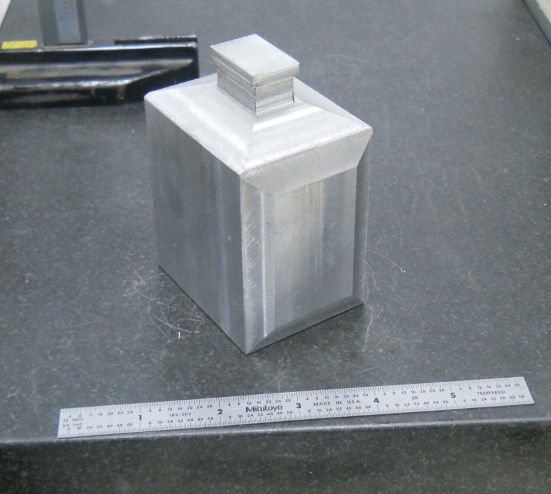 The next step is to bore out the cavity for a reflector and lamp, but that will wait until I acquire one and get its measurements. FWIW, it's better to machine the beveled sides before the top angles. |
|
|
|
Post by kvom on Feb 7, 2011 22:33:12 GMT -5
Yesterday's "work" was lots of filing of the spring bands trying to get the leaves to fit. Seems I milled the openings a little too small. I think that in retrospect making the opening about .03 (half a leaf) deeper might have been a good plan. All four now fit pretty snuggly, but some more filing may be called for on final assembly/ Today I made the first of 4 center bolts that screw into the spring band and pass through the center of the leaves to keep them all in place. I started with .5" 303 SS and got this: 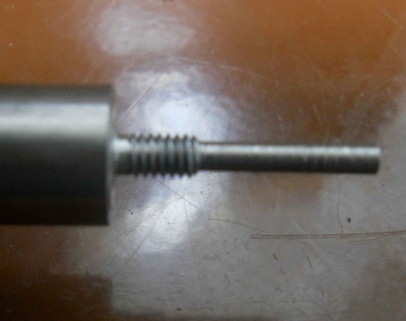 Then the same 5C collet was moved to the hex collet block on the mill to form the hex bolt head. I went with the 7/16 wrench size, although 3/8 might have been better.  After parting, I tried using it to assembled one spring pack and band. Getting it all lined up with such a tight fit in the band was a problem, and when the springs are cambered it will be even tighter. So more filing may be in order soon. So now I need to make 3 more of the same. |
|
|
|
Post by kvom on Feb 8, 2011 15:38:19 GMT -5
I got my package from POR15 yesterday, so now I can attempt to do some painting. POR15 is a rust preventing/restoring coating that is used a lot in restoring cars and other rusty metal. Given that steam locomotives are around steam and water, I figured rest prevention wouldn't be amiss.
Using this stuff is a multi-stage process. Now a friend and experienced builder told me to just use Rustoleum from the rattle can, that option seems too easy. The first stage for POR15 is degreasing, and the kit contains a cleaner called 'Marine Clean'. I diluted 2 cups with water at 5-1, poured into a flat plastic kitchen storage box, and submerged the 4 drivers along with several other pieces of scrap metal of various types. I'll use these scraps as test pieces before applying any paint to the drivers.
After soaking a couple of hours, the metal needs to be removed from the bath, rinsed off, and then sprayed with a 'Metal Prep'. This liquid etches the surface slightly enabling the POR15 to attach firmly to the surface. The metal surfaces get a thin coating of zinc phosphate. The parts are then rinsed in clean water and dried thoroughly. Any water getting into the paint will ruin it. I plan to put all the parts in the oven for a while at 200F to ensure complete dryness.
Now we apply the paint while wearing latex gloves, as it attaches itself very firmly to the skin. My starter kit has 3 1-pint jars, enough in principle to do everything I'v finished thus far. I plan to paint only the drivers at this time, once I'm satisfied that the scrap pieces look good. In principle POR15 gives a smooth, thin coating without brush marks when applied with a brush, so I'll see how that goes.
The final step is a top coat of paint, as POR15 deteriorates from UV if exposed to sunlight. My kit has 3 pints of a semi-gloss black that is supposed to adhere very well to POR15. if the results are as advertised, the resulting finish will be rustproof and extremely hard and scratch-resistant. I'll post pictures of my resuts later on.
|
|
|
|
Post by kvom on Feb 17, 2011 20:22:16 GMT -5
Having a chest cold over the past week, plus band trips for the kids, I didn't get much shop time lately. I did manage to paint the drivers with the POR15, and have been a bit disappointed with the results. The paint itself is not viscous, and a little goes a long way in coverage. I used a sponge "brush" to apply. On some flat test pieces the results were quite good, but with the drivers it dried a bit unevenly. I sanded the rims and other flat areas and painted on their black topcoat, but again the surface that resulted wasn't particularly good. I think spraying will work better once I get some equipment to do it. That said, I'll touch up the drivers again later. Today I tool the drivers to school to quarter them. I know traditionalists will scorn my use of Loctite, but I feel confident that it will work just fine. Yesterday I used Loctite 620 to attach each axle to one driver, letting it cure overnight. I had previously made a pair of aluminum jigs out of round. One end was turned to .500" to fit the crank pin hole, and the other to .875" to match the axle diameter. Putting the axle and attached driver in a v-block on a surface plate, I turned the it so that the top of the axle and the top of the jig were level, using a height gauge as the reference. The axle is then clamped into position on the v-block 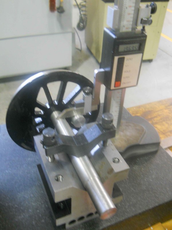 The crank pin hole is now horizontal with the axle hole to a quite good level of precision. The second driver has Loctite applied to the axle bore, and with the second jig in place was inserted onto the axle. On this side the jig and axle are aligned vertically with a machinist square, again with a good degree of precision.  The two crank pin holes are thus oriented at 90 degrees to each other (QED). The setup was allowed to cure for a couple of hours, although the Loctite would cure sufficiently to remove from the setup within 15-20 minutes. To ensure proper spacing between the drivers, I had made a spacer from some aluminum rod that I faced to 7.125". This rod was placed between the backs of the drivers when placing the second driver onto the axle. |
|
|
|
Post by kvom on Feb 20, 2011 17:19:59 GMT -5
Still fighting the cold, but the past few days resulted in two partially finished parts. I bought some more 1/2" CRS, so decided to attempt the eccentric strap for water pump. This has three separate parts, including the rod. The first half of the strap was profiled on the CNC mill. 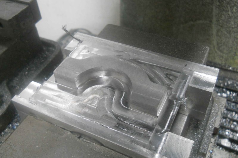 Then the part is chucked upside down on the Bridgeport, and the support material whittled away with a face mill. I rather like this method of "fixturing" as it results in a good finish on both sides.  The other half of th strap was machined the same way. Then with drilling and tapping, the two halves can be screwed together. I then faced both sides of the combined strap with the face mill to get the sides flat and parallel before going back to the CNC mill.  The center bore had been left a good 1/8" small when milling the halves, and now with them together the finish diameter can be milled.  Now the fit to the eccentric: 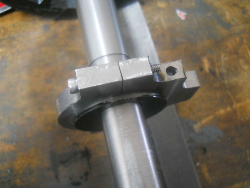 It's a little "tighter" than Kozo seems to like, but I imagine it will wear a bit early on. I drilled the oil holes before milling the bore, so what remains is to mill a slot for the eccentric rod, I started to mill the rod this morning, but broke 2 carbide endmills trying some new "techniques" and ruining the prepared stock, so to avoid depressing myself further I switched my attention to the front coupler pocket. Rather than soldering together various pieces, I intend to mill it from a single steel block. Starting with a piece of 1/2" square CRS stock, I milled the starting block to external dimensions on the Bridgeport. Here it is posed where the final piece will mount on the front bumper. 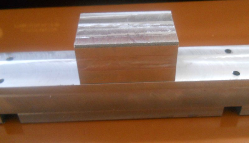 The first operation was the radius for the front: 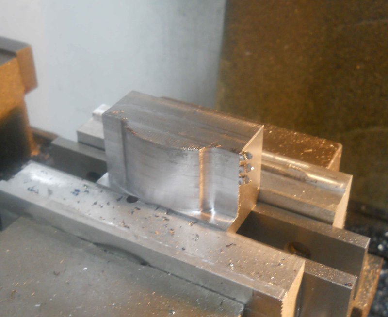 Then side flanges: 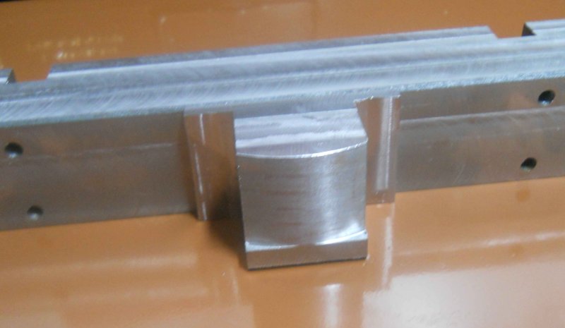 There are two pockets yet to be milled plus drilling and some other finishing. I'm not going to drill the hole for the coupler pin until I actually have a coupler to fit. |
|
|
|
Post by pkastagehand on Feb 21, 2011 16:38:41 GMT -5
Is your water pump eccentric bronze or cast iron? If the eccentric is steel and the eccentric strap is steel did you allow for some bearing material between? If not it seems like a possible trouble point later. Like materials running together is usually a no-no I've always thought.
Paul
|
|
|
|
Post by kvom on Feb 21, 2011 17:18:47 GMT -5
The eccentric is cast iron, harder than the steel. I had a discussion about this on Chaski before deciding on this combindation. Bronze would have been OK for the strap, but I couldn't find any raw stock of suitable size, ans the steel is a LOT cheaper. Today I finished up the coupler pocket. Did all the drilling on the Bridgeport - 1/16" corner holes for the main pocket (which may be unnecessary), mounting holes for 8-32 screws in the flanges, and a 5/8" hole in the center pocket for material removal. Then onto the CNC mill to mill out the coupler pocket. I retrospect, this would have been just as easy to do manually.  The bottom pocket and the bottom flange angles were milled on the Bridgeport. 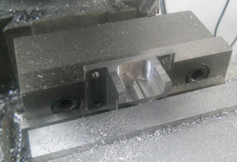 Ready for paint and a coupler for fitting. I can file out the corners if needed.  |
|
|
|
Post by kvom on Feb 22, 2011 17:44:37 GMT -5
With only an hour or so of shop time today, I contented myself with machining the slot in the eccentric strap where the rod fits. The plan specifies a rather awkward 5/32 width, for which I don't have an endmill. And in any case, milling a deep (.4") slot with a 1/8" endmill is not that easy either. So I decided to first cut the slot with a 1/16" slitting saw, and then widen with with a 1/8" endmill. While the G-Wizard feed&speed calculator gave a reasonable result of 180 RPM and 6 IPM, there was no real counsel on DOC. I ended up cutting repeatedly at .02, which took a while. Then my cheapo Chinese carbide endmill gave up the ghost after cutting a single pass at .015 DOC and 1 IPM. Luckily my medium priced Chinese endmill did survive to the end of the slot. So far I've broken 3 of the 1/8" 2-flute carbide endmills from Richon tools by barely breathing on them.  While their 1/2" carbide seems OK for roughing work, these small ones are just too fragile for anything. |
|
|
|
Post by kvom on Feb 27, 2011 20:00:51 GMT -5
I didn't get a whole lot of shop time over the past few days, but did machine the eccentric rod to go with the strap.  You can see where an overdeep cut with the slitting saw heated up the strap, but that will be painted over. While Kozo uses two screws to attach the rod to the strap, I decided to just use the Loctite 620, which worked well. I had bought some 2" square CRS a week or two ago, so I decided to start on the tee. i sawed of a chuck about an inch longer than needed, and machined the long sides to 1.875 x 1.625 as per the plans. Squaring the ends with side flutes of a long end ill wasn't a success, as I got a lot of chatter even with a very shallow DOC. I decided to see how it would work on the lathe anfd 4-jaw chuck.  I was a bit nervous with so much sticking out (7" with only 1" jaw length), but a facing cut produced a good result, even if the DOC was about .01". The length is still 3/4" longer than needed; I expect to mill to final length once the cylinders are present to be fitted. Since the piece is longer than needed, I milled the 4 slots using the center as the datum. 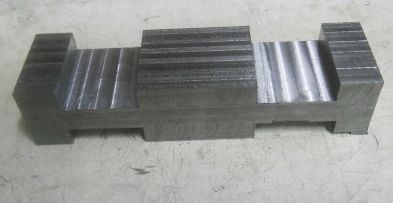 I need to drill two through holes lengthwise for steam supply and exhaust. I'll need to drill these halfway from each end. Given the facing cut on the lathe, I assume I could drill these on the lathe, but it seems easier to drill vertically on the Bridgeport. |
|


 While their 1/2" carbide seems OK for roughing work, these small ones are just too fragile for anything.