|
|
Post by ramkitty on Oct 21, 2010 19:57:54 GMT -5
thanks for the tips grege. I am still uncertain how to get it perfectly square but I guess I will bring out the dial gauge and reduce the runout that way.
The taper was small enough and I was impatient so I made one axle and its looking good. Locktited 2 wheels and the axle together.
I am pretty close to buying a mini mill for myself and I am looking at the LMS HiTorque Mini Mill since it has a bigger table and more travel as well as brushless. I have looked a little at CNC and it looks quite simple to do a swap. I am unsure how to do the Z axis control though since it is a different head design from the standard mini mill.
On that note I started looking at solidworks since one of the companies we deal with uses it extensively (possible job op in the future) I thought now is a good time to familiarize myself with the product. It is super quick and quite easy to design in 3D. My last real CAD experience was with autocad 14 over a decade ago. Following a tutorial I was able to to learn enough to design a hinge. Moving the parts in 3D was really cool. The best part is I can pass it off as work 'research'. Using my newer skills I set out drawing the journal boxes in 3D. Extruding the basic shape and cutting out the frame notches is very quick. I then applied the bushing bore and used the whole wizard to place the 3-48 screws in the top. The dimensions are set and everything is dynamic based on relationships. The bore hole is set to the center of the part while the screw holes are horizontal to each other spaced x (3/8?) amount from each other centered in the notch in both the x and y directions. I had almost completed the part but realized that I could have done it in a better way so I backtracked almost the the start. Next I have to mirror the notch and screw holes across the center line of the part and from the right side draw the cutouts and cut across the thickness of the part to complete my first part. From here making mechanical drawings is very quick since the dimensions are dynamically determined. If I choose to draw the remaining tender truck assembly I can physically assemble the train in 3d digital space much as grege has on this forum elsewhere.
|
|
|
|
Post by grege on Oct 22, 2010 6:39:20 GMT -5
The other Greg - GregMiller - is the builder using solidworks to model an A3a. The cad work I've done for this project has just been 2D in AutocadLT. I'm using the more recently up to date 2002 version  |
|
|
|
Post by phutcheson on Oct 22, 2010 14:23:57 GMT -5
ramkitty,
Couple of thoughts on your issues...
I used SS303 for my axles, cuts nice and won't rust. But W1 should also cut nice ... so I'm a little concern why the chatter. Maybe the material is not W1 (or it has been harden already) ... and/or a loose gib or tool. Dull tool. Stock too far out ... mine was out about 1". Take small cuts .010 or less. Then .0005 near the end to get the final diameter. Cut to the shoulder leaving about .001" for a finish cut. Changed to a small bladed cut off tool for the under cut and shoulder finish cut.
I don't use the compound unless I need a chamfer .. I just use the Cross slide. This should eliminate any taper for that .75" length. If not, set up the compound to offset the taper (test on a scrap piece of material). The other aspects I follow the book and greges method.
For the runout ... I changed to a 4 jaw chuck to get the TIR < .001".
You can see my results on my website (not all that great). But I have learned a lot since then and think that if I were to make the axles and other parts today ... they would be a lot better.
I also use SW for the Engine part (not the Tender) and it really gives me an insight on what to expect ... before I cut. There a few pictures on the website.
Later,
Pat H.
|
|
|
|
Post by ramkitty on Oct 22, 2010 19:26:19 GMT -5
spent the day learning solid works. I have a reasonable grasp of it now. This is what I got done today ;D If only I could build the actual hardware this fast.  I am unsure how to get the holes to not always show up like they do. And springs were a pain in the ass to learn how to mate with the parts. |
|
1hand
Gandy Dancer

Posts: 6
|
Post by 1hand on Oct 23, 2010 9:54:22 GMT -5
Hey that's really cool. I'm trying to learn CNC. I did a conversion on my mill last winter, and been gone on the road working ever since, and have forgot everything I learned. So now back home for this winter I'm converting my lathe and try getting it all up and running to start the A3.
Matt ;D
|
|
|
|
Post by GregMiller on Oct 24, 2010 12:33:05 GMT -5
Hi, This is the other Greg... Greg Miller I am actually using Alibre rather than Solidworks, but I imagine that they are similar in usage. I used AutoDesk Inventor for awhile at work, and transitioning to Alibre at home was pretty easy. Greg |
|
|
|
Post by ramkitty on Oct 25, 2010 19:04:00 GMT -5
 time to get back to actual machining I think. I have figured out some measurement tricks such as basing the bolster widths based on the total width of the tender and the thickness of the side sills. This was important because I am pretty sure I have to change to 3/8 as there is some weird metric conversions. |
|
|
|
Post by phutcheson on Oct 26, 2010 11:43:48 GMT -5
ramkitty....
What are the steps to post pictures here on this forum?
I have a few that I would like to share.
Thanks,
Pat H.
|
|
|
|
Post by ramkitty on Oct 26, 2010 15:56:49 GMT -5
I have been using picassa a free google product. picasaweb.google.com/home They provide some web space for picture uploads and once you upload an image you can link it in using the image tag. To do so you navigate to your photo (on the web, you can use your own webserver which you have up) eg the journal box link www.phutcheson.net/images/A3%20Switcher/J%20Box%20Bearing%20Columns/Journal%20Box%20995.jpgyou then encase the picture with the image tag (-the.) [.img][./img] to get the following  if you are using picassa you get the link by viewing the picture on the right there is a link to this photo and use the embedded image with the image link only in the desired image size. |
|
|
|
Post by ramkitty on Oct 28, 2010 22:26:18 GMT -5
I got a bunch more metal in today too. Stock for the tender frame and truck bolsters, hex stock for most of the project most of the pump stock and the stock for the fire grate and bits. I received the remainder of most of the brass screws needed as well as the last of the taps too. Expensive little suckers but fasteners are, I built an adarondac rocking bench and the wood screws were expensive and they were nothing special I figured it is a good place to get some simple milling practice.
I lathed the tender frame to length as I think I will build it sooner. Do you guys use the milling machine for drilling the holes to fix the frame or punch and use a drill press? I am unsure how to address the holes in the end of the frame.
I also realized that I know very little about milling machine operations. Where would be some good recommended reading. I used mini-lathe for a bunch of lathe info but they dont have much for milling. I know about about using an end mill but drilling with the milling machine. Do you sketch layout lines and cut to the point as a rough and finish with the dials? Do you use a prick/center punch on holes to drill followed by a center drill... like the lathe? I have to make a tap guide sooner too since I am getting to the point where I will need to start fixing parts.
|
|
|
|
Post by phutcheson on Oct 29, 2010 2:53:42 GMT -5
ramkitty,
Thanks for the how to insert a picture... I will give it try.
I use my mill to drill holes ... I layout, center drill then drill. If it is a tapped hole I will tap it using the mill but not under power. I have a DRO so I get the location just right ... but I still will layout first. Depending on the accuracy needed I may use the layout as a starting point then use the dials (DRO in my case) to get the next point. Or I will use an edge-finder then the dials.
Take a look on my website how see how I did the frames under Tender Frame section 4 and other sections for set ups and mill/lathe work. There are lots of ways to machine a part ... I will study the part/assembly then review how I may machine it, review other methods before I start. Of course your method (as did mine) will depend on what tools you have and what you are willing to spend.
You might try the bookstore for magazines, search the web as there are lots of how to methods. Other builder's pictures here on this forum and other forums (even if is not a train). As you know a picture is worth a thousand words! Also look in my guest page there are a bunch of pictures of an A3. Local college my offer courses using the mill/lathe.
Later,
Pat H.
|
|
|
|
Post by ramkitty on Nov 6, 2010 9:48:48 GMT -5
More progress made. I started using the milling machine beginning by working the drawbar pocket and the truck bumber things. Something simple and easy to get used to the milling machine. I had some issues milling a little too much on one side of the pocket and went to deep on a pair of the bumpers. The milling machine has some weird lead screws. The x and y are both 120 thou per rotation y has 1 thou per division and y has 2 per. The z is terrible at 40 thou per division. I use a micrometer to get a real depth. Yesterday I went further and did all the holes for the front and rear bumpers. I know have my first bolt together parts. A lot of chucking operations to do all the holes. Monday I will try to finish the tender frame as I only have the holes in the side sills to drill and the end holes in the bolsters. I will use phutchesons technique of mounting the side sills but I think I will need to use the drill press since the mill is a mill/lathe and the head is over the bed not providing the clearance needed. I need a real mill. On that I must have planted the seed right because yesterday my wife asked if I ordered it yesterday. She said it can be my xmas present but I have to order it so I get the one I want. ;D I love my wife. I will also get the tormach quick change tooling holders with more than one chuck seing how many holes are required in this project. I guess more pictures are to follow. I will post some when I finish the axles. EDIT: I went to order the mill and they were backordered  they had stock on thursday oh well I guess I am waiting. Or I could upgrade to an x3 type mill |
|
|
|
Post by phutcheson on Nov 9, 2010 11:42:18 GMT -5
Go the upgrade ... you won't regret it. 
Pat H.
|
|
|
|
Post by Harlock on Nov 9, 2010 14:12:40 GMT -5
Congrats on your new mill. I have discovered that my HF Mini Mill is not really usable for actual milling without a lot of improvements. The dials and lead screw like yours are an odd ball 62.5 thousands per revolution, so 1/8" per two revolutions, and the Z axis does not hold calibration once you back it off, due to the way it is inherently made. I asked on the HF Mini Mill group about how to tighten it up, and basically understood that it is the way it is. So even if I add a DRO, it will still be pretty limited. I've had a lot of clearance issues plus issues with rigidity, although for small brass parts it's been fine.
My plan is to eventually replace it with an RF-45 clone (Enco) which is a larger square column bench top mill with a 21" table, pretty much as big as you can go before stepping up to a knee mill. On my advice my father bought one and he has been happy with his.
|
|
|
|
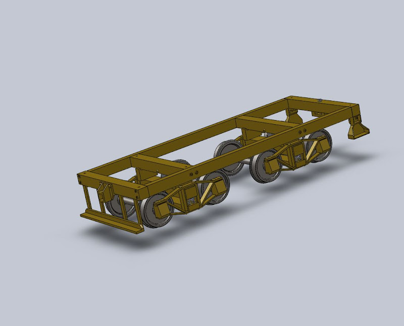
Post by ramkitty on Nov 9, 2010 22:54:16 GMT -5
you twisted my arm ;D I ordered a grizzly small mill grizzly.com/products/G0463It is the x3 mill with a 21x6 table and .1/turn dials. I will play with it for a while and then see if I am still going to cnc conversion. I also finished the main frame. I have to build the coupler pocket and footboard. I will go back now and finish the trucks and axles. I also received my backordered sheet stock so I have most of the mats for the rest of the tender. I cant find the .1 stainless wire for the handrails and a few other small like the copper tubing and other plumbing stuff. |
|


 they had stock on thursday oh well I guess I am waiting. Or I could upgrade to an x3 type mill

