|
|
Post by kvom on Dec 21, 2010 20:57:48 GMT -5
It seems to me that the main function of the retainers plus the two piece boxes is the ability to remove the bar and the lower bearing half to re-lubricate the stuffing for each bearing. Today I needed to mill the pocket where the lubricated cotton is placed in the axle box lower half. I did these on the CNC mill after first verifying the program on a piece of aluminum scrap.  Then I decided to make a start on the brake lever bracket (drawing 6 on p213). The first step was to mill some 1x1x2" bar to nominal piece dimensions, and then drill the 5 through holes in each. Then two two mounting holes (8-32) were counterbored. Again, all done on the CNC mill.  Then I mounted a piece of aluminum in the vise, and drilled/tapped two 8-32 holes to match the holes drilled in the parts. I then attached the brackets to this fixture with 8-32 SHCS.  The outer profile of the bracket could now be milled using a 1/2" 4-flute endmill @ 1200 RPM. I kept the feedrate down to less than 10 ipm, although I suspect it could have been done faster.  The result of a couple of hours shop time:  The rest of the work on these parts will be done manually on the Bridgeport. No further progress foreseen here until after Christmas. |
|
|
|
Post by kvom on Dec 27, 2010 17:59:50 GMT -5
Back from Florida, suffering a head cold, so not much time in the shop this afternoon. I finished up the brake lever bracket, which involved primarily milling slots. With a 1/8" endmill in steel, you can't push it; so the narrow slot was .025 DOC at 2ipm. I'm glad the BP has a table drive, else that's a lot of cranking.  I did manage to do some CAD/CAM on some other brake parts to be done later this week. |
|
|
|
Post by kvom on Dec 28, 2010 21:40:30 GMT -5
I got 1-1/3 part done today. The 1/3 part is the center section of the brake lever beam. Making this was a bit of a PITA, but it came out OK in the end. I used the same 304 stainless bar as for the fire grate:  It's a tight sliding fit onto the beam that I made previously. I will eventually fasten it permanently with green loctite and possibly a roll pin as well. The other part is the brake pedal bracket (fig. 3-12 on p. 215). The first operations are on the CNC mill on a piece of CRS 2.5x1.4x1.3.  Then after removing the remaining "corner" remnant with a hacksaw, the bottom section could be machined off on the Bridgeport:  After a bit of filing to cleanup the edges, I drilled the 4 through holes for 8-32 screws:  Then after countersinking two of the holes on the bottom, a test fit onto the frame footplate:  It seems to me that some of these parts are drawn for elegance of form, as they are not easy to machine as drawn, and a simpler, more oblong profile would work just as well. |
|
|
|
Post by kvom on Dec 30, 2010 22:09:37 GMT -5
After an off day yesterday, I had almost an entire workday in the shop today while all the women were out of the house. Seems there should be more to show somehow. The productions were 4 parts of the brake pedal as drawn on p. 215, plus the bushing for the brackets. I just used a 1-piece bushing with a press fit rather than the 2 pieces loctited to the bracket.  It still packs the actual pedal piece, as I don't have proper size material. I'm also unsure if a Mapp gas torch will heat the steel bar enough to bend 90 degrees as stated in the book. The design also defers connecting the two sliding parts of the lever bar until final install, so as to orient the pedal at the proper angle for comfort. |
|
|
|
Post by kvom on Dec 31, 2010 20:06:54 GMT -5
I purchased a lathe tool for cutting the profile for 7.5" gauge train wheels from a builder on the Home Machinist board, so I am now in a position to cut the flange and tread on the iron driver wheel castings. To ensure concentricity with the 7/8" center bore, it's necessary to turn a mandrel that's a good sliding fit for the bore. The first task was to turn an aluminum washer for clamping on the mandrel, and I made this from a piece of 1-1/8" aluminum, drilled for a 1/2" screw and parted off .3" thick. I then turned the mandrel from a length of 1-5/8" aluminum, taking the last cuts .001 at a time until the fit was achieved. As I had reamed the drivers, I found that all had the same good fit as the first. I then drilled the center of the mandrel for the 1/2-20 screw I found in my bolt bin (1/2-13 seemed too hard to thread as my tap is a crappy carbon steel one). Not wanting to experiment with a $75 casting that has a lot of work in it already, I had previously made a blank "wheel" from some 3" aluminum round, drilled and reamed to the same bore as the castings, and hence a good fit for the mandrel. Here's the trial wheel mounted:  Rather than a full cut with the profile tool, I turned the blank to 3 separate diameters: 1) Flange diameter fully across 2) intermediate diameter .25" less and .156 from inner edge of the wheel 3) tread diameter .375" less than the flange and .234 from the inner edge I then used the compound set a 3 degrees to turn the tread, stopping at the edge of the intermediate cut  Now the profile tool is aligned with the inner edge:  Finally I advance the cross feed slowly until the outer radius meets the tread. Even being aluminum there was a fair amount of chatter. It looks as if I needed to go in a couple of thou more, although I doubt it's critical.  After a little polish, I can take this to the club's new years day party to get feedback from the other members.  Of course, the mandel will remain chucked on the lathe until the drivers are finished. The edge opposite the flange will also be rounded off. |
|
|
|
Post by fender on Jan 2, 2011 11:49:21 GMT -5
Hi, I have used a similar flange profile form tool. There are two things you can do to reduce the chatter. One is to put a machinist's jack between the bottom of the tool and the cross-slide. This will increase the rigidity of the tool: www.use-enco.com/CGI/INSRIT?PMAKA=827-9360&PMPXNO=2859541&PARTPG=INSRHIThe other is to slow the lathe down to the lowest spindle speed. With a lower speed, the chatter marks will be closer together and less noticeable. |
|
|
|
Post by kvom on Jan 2, 2011 19:17:45 GMT -5
The problem was that the center screw didn't provide enough friction to resist the driver turning on the spigot. I was advised by a member of another forum that I should be using a faceplate for forming the flange, using a bolt against one of the spokes to prevent the wheel from turning. That sounded perfectly reasonable, except that I don't have a faceplate for my lathe. What I do have is a dog driver that I bought used, and that came with an aluminum fixture place that bolts to it. So my goal for the day was to concoct a way of mounting the drivers on this plate. I first sliced off a 1" thick piece of 3" aluminum rod, then faced it on both sides on the lathe. On one side I formed a spigot and flange. The flange I drilled and counterbored for 4 10-32 screws:  The next step was to drill and tap 4 matching holes in the fixture plate, then screw the two parts together:  The ensemble is bolted to the dog driver, then mounted on the lathe spindle (D1-3):  I could then turn the spigot down to a sliding fit for the drivers plus drill and tap the center for the mounting screw. By fitting as driver, I could drill and tap for the driver screw, also 10-32.  Now with the assembly mounted on the lathe, I could put the drivers securely in place and turn the flanges. This went really well and much faster than for the previous method. I ran the lathe in back gear at 100 rpm, and had very little chatter. I also was able to cut the "paint line" in the counterweight.  While this fixture took most of the afternoon to concoct, it will be useful for the next step, which is to drill the crankpin holes. I made this D1-3 mill mount some time ago to allow work to be moved from lathe to mill without unchucking:  So with the mount clamped to the mill table, I'll be able to ensure that all four drivers have their pins the same distance from the axle bore. The driver screw will also act to position all 4 at the same angle.  But that's for another day. |
|
|
|
Post by kvom on Jan 4, 2011 8:29:42 GMT -5
I finished the drivers by drilling the crankpin holes, using the setup from the previous post.   While doubling Kozo's plans would mean the crankpin is 9/16" diameter, I am using 1/2", as I have a reamer for that size. Shouldn't make a difference. I made a start on the brake lever links, but was unable to finish yesterday. I'll post pics when they're done. |
|
|
|
Post by pkastagehand on Jan 4, 2011 12:12:15 GMT -5
Good progress!
I don't know about you but I always hate it when I have to do multiple parts though. Too much like factory/production work. I like working out the puzzle of how to do the first one.
Paul
|
|
|
|
Post by kvom on Jan 4, 2011 15:19:19 GMT -5
CNC makes multiples a bit less irritating, witness today's fabrications: Yesterday and today I worked on the "brake lever links". These parts, two mated on a side, transmit braking force downward, which spreads the ends apart. The ends are attached to the brake levers, which in turn press the brake shoes against the wheels. The profile of each part is the same, so the first step was to CNC mill that profile into some pieces of 1/2" thick CRS. Each part is a bit over 2" long.  Next I mounted aluminum soft jaws on the vise and milled the same profile as a pocket. Note that the jaws are clamped on a thin piece of material while being milled so as to provide some room to actually clamp the piece firmly.  Now each piece can be clamped in the pocket:  And have the "substrate" milled away:  The same pocket is then used to drill each end of each part.  And the final CNC operation is milling the cheek cuts on two of the links:   Then after filing the burrs, I milled the slots on the Bridgeport using a 1/8" carbide endmill. In retrospect, I could have done them faster with less tedium via CNC:  The profile could have been milled manually using angle blocks; the side angle is 3.1 degrees, but CNC makes parts like this a lot easier. |
|
|
|
Post by phutcheson on Jan 4, 2011 21:48:44 GMT -5
It sure does! 
Nice work!
By the way what CNC machine do you use, program etc.
Thanks for sharing!
Pat H.
|
|
|
|
Post by kvom on Jan 5, 2011 8:26:19 GMT -5
Mill is a Novakon NM-200, which I've had for about a year. No coolant yet, but I'm thinking of adding it this year. 3HP motor, 4K spindle. The setup for small parts is a CI tilt table mounted with 2 4' Kurt vises spaced 4" apart. The fixed jaws are trammed so that I can mount fairly long pieces using the two vises.
I'm using DraftSite for 2D CAD (free download) to draw the parts and export as DXF, then CAMBAM for generating g-code.
|
|
|
|
Post by kvom on Jan 6, 2011 14:11:07 GMT -5
The latest installment is machining the brake levers. These parts attach to the lever brackets, lever links, and brake shoes (all shown on p. 213) via pins secured by e-clips. I decided to CNC drill and mill the profiles for all 4 copies in the same operation, using a piece of 12L14 recovered from the school scrap bin. I did spend a fair amount of time in Cad moving the pieces around to fit on the stock with somewhat minimal wastage. The first operation was to mount aluminum softjaws on the vise, as I would be milling/drilling through holes. I machined a ledge in the jaws to support the work.  Next, the drilling and milling were done. Here the CAM program left holding tabs to keep the parts attached to the stock. The tabs were .1x.1", specified so that they would be removed in the final milling operation.  The profile didn't cut through the material, so I must have miscalculated something; however a facing op on the Bridgeport to remove a few thou from the bottom exposed the part profiles. Then a few minutes work with a hacksaw cutting the tabs left the parts free.  Now I machined the tops of the vise softjaws flat and milled a pocket .120" deep using the profile of the part. Afterwards I found the parts wouldn't fit. It was necessary to rerun the CAM program specifying a negative roughing allowance of .005, which in effect expanded the entire profile by that amount. Now the parts fit securely. Note that for these types of operations the pocket needs to be the mirror image of the part. 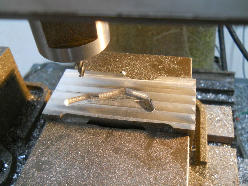 Machining the "bottom" of the parts brings them to the correct thickness as well as removing the tabs. Again the CAM program specifies milling wider than the profile to avoid burrs on the edges.  Finished; this material machines a lot nicer than the CRS I used on other parts so far:  |
|
|
|
Post by kvom on Jan 9, 2011 17:45:58 GMT -5
Today's part was a pretty quick and easy one once I got into the shop. Again, using CNC with holding tabs to mill out the profile, then filling off the tabs once cut free:  I don't have any 1/8" steel, so anticipating obtaining some I am drawing up all the different spring hangers from p210. I plan to cut all of them from one piece of stock in one CNC run. Expecting snow and ice today and tomorrow.  |
|
|
|
Post by kvom on Jan 12, 2011 17:34:42 GMT -5
I got the spring bands done over the past two afternoons, then fitted the stirrups to the axle boxes via a bit of filing.  I've got the spring steel on order, as well as some 3/16 drill rod for the pins. These pins take e-clips, and hopefully the grooving tool I ground last year to cut some model cylinder fins will work on the clip grooves. As we've been snowbound here in Atlanta for the past few days, I've spent the time drawing the various parts in CAD. So there's no lack of parts to make when I have suitable stock. I think the valve gear and rods will likely be stainless until proven otherwise. |
|


