|
|
Post by Harlock on Aug 7, 2006 20:37:22 GMT -5
Bill, I'm well versed in solidworks. What are your plans for the files? Are you willing to share them? I had entertained the notion of building a 3D version of my switcher as I go, so that when I'm done with the real thing I'll also have a perfect model in SW with gear motion that actually functions in the assembly. But I couldn't figure out why I would go to that trouble, because Kozo's book is so good, it doesn't really need much help that I can see so far. Unless you have CNC equipment of course. Then it could be most useful.  I just have the basic stuff... --M |
|
|
|
Post by Bill Holland on Aug 7, 2006 22:11:28 GMT -5
My reasons for doing it are simple, I will be away from my machine tools for a long time as I go back to college for Air Traffic Control. I need to do something with my spare time, Im hoping solid works will hold me over.
I would post the files but anyone with solid works could pull all the measurements right out and build the locomotive without ever having bought the book. I dont think Kozo would appreciate that very much. I will however post pictures. I just finished the cylinders and steam chests. Really is an amazing program. By the way, doing the Kozo A3 is one good way to learn the program, I've only been playing with it for a few weeks now.
|
|
|
|
Post by Bill Holland on Aug 8, 2006 11:23:24 GMT -5
Sorry if this was mentioned already. In solidworks I discovered an error in the drawings for the steam chest covers. The screw holes should be .125 away from the edge. With the dimensions Kozo gives, you notice the 4 bolts on the short ends are not close enough to the edge.
|
|
|
|
Post by patyoung on Aug 8, 2006 15:57:27 GMT -5
Hello Bill and Harlock,
There is a very good reason I am putting the A3 into CAD format. It can be used as a
starting point for many variations. The A3's drive mechanism can be lengthened and
made into a 0-6-0 switcher with some modification. I personnally plan to use the drive mechanism as a starting point for a 2-4-4-2 articulated locomotive. Think of how hard
it would be to do this by hand. Much can be learned by just building the A3 in CAD.
I'm putting the Fitchburg Northern into the computer to do some modification like
enlarging the drivers. I hope this is how our hobby will eventually move towards.
Just my .02 worth of rambling.
Pat Y.
distilled
|
|
|
|
Post by Bill Holland on Aug 8, 2006 17:28:48 GMT -5
Bill, I'm well versed in solidworks. What are your plans for the files? Are you willing to share them? I had entertained the notion of building a 3D version of my switcher as I go, so that when I'm done with the real thing I'll also have a perfect model in SW with gear motion that actually functions in the assembly. But I couldn't figure out why I would go to that trouble, because Kozo's book is so good, it doesn't really need much help that I can see so far. Unless you have CNC equipment of course. Then it could be most useful. I just have the basic stuff... --M I plan on making quite a few of my own designs while Im in Florida, one thing on the block is a Ge 44 ton locomotive, another is a 2-6-0 alco of the Skaneateles Railroad, and perhaps drawings for a form for a more realistic A3 driver casting. These I will just offer straight up for download under the GPL free software license agreement. I believe in open software and content. Ofcourse none of those drawings will have had their prototype built, oh well. |
|
|
|
Post by efbernardc on Oct 21, 2006 20:10:06 GMT -5
for the A3 switcher. Page 63, Fig. 9-32 calls out a 3-47 clamp, should be 3-48. This probably a typo, not a true mistake.
Page 73, Fig. 11-15 shows a 9/16 reamer being used to reream the bushing bore. This clearly should be a 7/16 reamer.
|
|
|
|
Post by treinenbaas on Nov 12, 2006 15:49:57 GMT -5
Tender Trucks in 1.5" scale.
Has anyone completed the trucks? I am looking for the bolster spring dimensions. Did I mis them or did Kozo fail to give them.
|
|
|
|
Post by treinenbaas on Dec 1, 2006 11:06:47 GMT -5
Is there anyone out there that has info on the bolster springs for the 1.5 scale tender?  ? I posted a message on Nov 12 with no replies. Did I post in the wrong category? ? Gerry |
|
|
|
Post by efbernardc on Jun 4, 2007 22:00:52 GMT -5
Page 132, Fig 23-1 Smoke tube diameter is called out as .787OD.
Page 173, Fig 23-11 Holes bored in front tubesheet for smoke tubes is .752 for .750OD tubing.
|
|
|
|
Post by efbernardc on Jun 4, 2007 22:03:30 GMT -5
Page 132, Fig 23-1, smoke box stud hole diameter in front tube sheet is 1/4in.
Page 137, Fig 23-11, smoke box stud holes are to be reamed to 7/32in.
|
|
|
|
Post by efbernardc on Jul 29, 2007 21:56:06 GMT -5
25.12 Smokebox bottom cover
See pages 83, 152 and 160
The bottom cover needs notches to clear the cylinder attachment bolts.
Regretable as the smokebox isolates the hot steam "Tee" from ambient air.
|
|
|
|
Post by siggy on Oct 22, 2007 16:29:45 GMT -5
25.12 Smokebox bottom cover See pages 83, 152 and 160 The bottom cover needs notches to clear the cylinder attachment bolts. I just ran into this one myself. Pretty amazing that this is really the first non-trivial error in the whole process so far. In my book that's quite a testiment to Kozo's plans. Even so, it was very easy to work around the issue without scrapping any parts. Robert 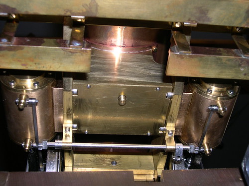 |
|
|
|
Post by efbernardc on Oct 29, 2007 21:15:24 GMT -5
Pennsylvania A3 Switcher, Bell Lever, 29.7, page 176.
The hole to hole length should be 5/8, not 5/16.
|
|
|
|
Post by efbernardc on Jan 29, 2008 13:43:06 GMT -5
Pump Body Figure 8-3, page 52 and Tank Floor, page 32 Figure 5-3.
The pump would be easier to mount and holes easier to seal if the pump base were threaded and the tank floor had clearance holes.
|
|
|
|
Post by efbernardc on Jan 29, 2008 13:45:52 GMT -5
Coupling Joint, page 193, Figure 33-10, part 11.
The hole diameter for the water tubing should be 3/16 not 5/32.
|
|


 I just have the basic stuff...


 ?
?