|
|
Post by kvom on Jul 18, 2012 15:40:06 GMT -5
I liked the skateboard wheels since one package has 8 wheels and 16 bearings for $35.
The wheel surface is rounded, so actual contact area on each is fairly limited. No idea if flat spots will develop.
I separated wheels by 5 inches on each driver, meaning that the low point of the driver is .70" below the top of the wheels. The wheel centers are .75" below the top edge of the treadmill frame, so that the bottom of the driver is still above the frame. Therefore, the brakes should be able to fit with the loco on the treadmill. Brakes and springs will be attached next.
|
|
|
|
Post by kvom on Jul 20, 2012 17:41:27 GMT -5
Today was just dedicated to trying some things for fit. Used the engine hoist to put the loco and boiler together on the floor, and positioned the tender behind:  Because the plans for the 1.5 scale boiler place the steam dome further forward proportionally than for the 3/4" scale, the throttle tube into the can will be longer. I measure 5" from the rear of the dome to the front of the cab. Sitting on the rear of the tender, I would have quite a stretch to reach a throttle that was just inside the cab, so the tube will likely be extended in the cab at least 2-3" and will need to be designed not to interfere with whatever the turret turns out to be. Here's a shot taken at eye level with me sitting on the tender: 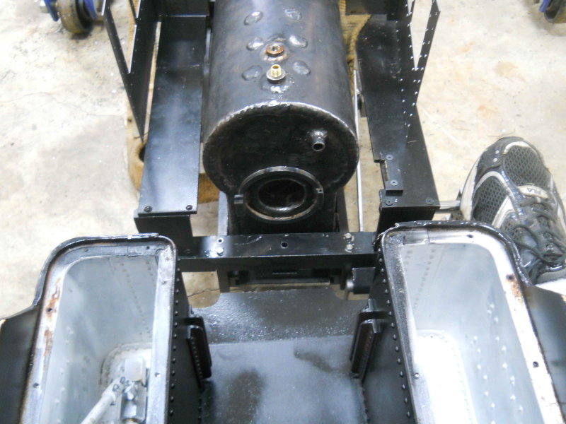 It seems that the manual foot-operated brake lever will work well with my shoe resting on the tender footrest. OTOH, getting a good view through the firedoor will require scrunching over. Adding a seat or cushion will make me sit even a bit higher. Stoking looks as if it will be fine. The front of the tender and the loco's rear footplate are pretty much on the same level. Kozo doesn't use an apron on the small loco, so I'll need to make something. The tender's provision for a drawbar is about 1/4" lower than the loco's. |
|
|
|
Post by kvom on Jul 24, 2012 16:51:14 GMT -5
Spent the last shop sessions making the drawbar and drawbar pin. To adjust the fit I used the auto lift to position the tender frame level with the loco so that the front tender truck was on my booty-fab track:  The attachment for the tender drawbar is not readily accessible with the tank in place, so I had to remove it termporarily. There's about 1" of space between the tender's bumper and the loco's rear footplate. Any closer would interfere with the foot brake. |
|
|
|
Post by kvom on Jul 25, 2012 16:00:04 GMT -5
I will need to mount my AME lubricator on the front of the footboard rather than behind the yoke, as Kozo shows. That's because it's wider than Kozo's and thus would interfere with the reverse reach rod. So now the activating motion will be the valve rather than the eccentric strap. The value travel at full gear is .6". OTOH the lubricator lever needs to move only about 10 degrees to advance one notch, meaning that the lowest hole on the pivot arm will move about .32". To account for this, I've made a "lost motion" strap to fit to the lever arm:  The 5-40 screw in the rounded end adjusts the travel in the slot. The other end will have a 1/8" diameter rod approximately 2" long connecting to the fork at the end of the valve rod. Since the lever will be a bit outboard of the valve, the connection will need to be offset from the valve approx. 1/2". I have some ideas on how to do that once I mount the lubricator to the footboard. The holes in the lubricator's arm would be best fit by a 3-48 screw, which I don't have. For the time being I'm using a long 2-56 to fit. |
|
|
|
Post by kvom on Jul 26, 2012 15:15:17 GMT -5
Today's project was to finish the lubricator linkage. The photo is pretty self-explanatory:  Rolling along the track with the adjusting screw all the way in appears to advance the ratchet two teeth, which is what I expected with full-forward gear. I still need to bore a hole in the footboard for the filler cap, plus get a shorter/different screw for the lever attachment. |
|
|
|
Post by kvom on Aug 30, 2012 16:19:05 GMT -5
Got back to work on the loco after a break. "Final" throttle design will have a tube connecting the steam dome with the turret, with the tube being under steam pressure. I ordered a 1 foot piece of brass tube from McMaster; it's 1/2" Nominal but actual OD is .840" and ID is .622. This will give clearance to a two-piece reach rod activating the globe valve. Today I made two flanges that will be silver-soldered to the tube. I spiral milled the center hole, the first time I'd used that technique on the CNC mill.  |
|
|
|
Post by kvom on Sept 6, 2012 13:04:32 GMT -5
Further work on the throttle mechanism: since I'm trying to design as I go, I sometimes feel like flying a bit blind. So I bashed together the following activation mechanism that would be attached to the turret when built.  I drew it up in CAD trying to assure that I would get sufficient travel from the reach rod. It looked good on paper, so spent a half day machining the various pieces to verify. The globe valve that meters the steam has a 90 degree spindle travel from full-closed to full open. With a 1" crank bar, that means a 1.4" lateral travel of the reach rod. To minimize the vertical displacement of the end of the crank, its closed position is 45 degrees from vertical. Given that the throttle bar would be pulled backwards to admit steam, the closed position is as shown in the photo. I machined the top portion of the bar at a 10-degree angle from the bottom, as that was the most I could get from the piece of brass I started with. However, I may remake it with a greater bend if needed once I have the turret made. After some advice from other builders, I will make the 2-piece reach rod from stainless steel rather than brass. I also need a different connector for the end since the "fork" reduces the travel distance. |
|
|
|
Post by kvom on Sept 17, 2012 18:28:01 GMT -5
After some more discussion on the steam dome with an experienced builder, I started on fabricating the "can" components that will be welded to the boiler. The first issue was that the flange I had originally was too thin. The tapped holds that secure the cover should not be through into the steam. Therefore I turned the flange off the can leaving a simple cylinder 3.375" OD with a 1/4" wall. Now I need a ring that will be welded to the can to form a 1/2" thick flange 1/2" wide, meaning that the OD will be 2.375". I started with a piece of 5/8" thick HRS about 4" square, faced both faces with a facemill on the manual mill, and milled two of the sides square. Now I could mount the stock on the CNC mill to remove the center material. For this, I wanted to try something new to me. My CAM program allows me to easily draw a flat spiral with any given distance between the loops. So using a 5/16 endmill and a .03" spacing (9% engagement), I would be able to mill at full depth using just the side flutes. This is a type of "high speed machining'. To start, I used a 3/8" endmill to spiral drill a .6" diameter center hole, and then the spiral. A finish circular path brought the hole to its desired diameter.  Total machine cycle time was about 15 minutes. For the OD, I could have programmed a profile cut in CNC, but a large endmill would have cut into the vise soft jaws, and a smaller endmill would have meant a slot depth greater than the tool diameter. So I decided to use the lathe. First I needed to round the corners as much as possible with the manual mill. Here's the setup for the first pass:  After trimming 4 corners I mounted the work on the lathe as shown here. I used a pair of 1/8" parallels to space it away from the jaws to avoid cutting them.  Then I turned it to slightly larger than final dimension, faced both sides, and chamfered one outer edge to allow a space for welding filler.  The cover mounting holes will be drilled and tapped after welding an cleanup. |
|
|
|
Post by silversanjuan on Sept 21, 2012 22:48:41 GMT -5
It's lookin' great Kevin. Have you finalized the design of the throttle?
Todd
|
|
|
|
Post by kvom on Sept 23, 2012 20:00:33 GMT -5
The next part for the throttle is a flange that will be welded to the steam dome "can" and mate with the brass tube/flange. This piece is made with 316 stainless. I started with a 1-7/8 diameter by 1" long round bar, face both ends on the lathe, and through drilled a 5/8" hole. Then I milled a pocket in the CNC mill soft jaws to hold the bar, and milled the profile and enlarged the center hole to .90". Finally drilled two holes to be tapped 10-32. Here's the result this far.  |
|
|
|
Post by kvom on Sept 26, 2012 13:10:49 GMT -5
After tapping the two mounting holes, I attached the flange to a piece of aluminum with screws and set up as shown below. Then the back of was milled to match the diameter of the steam dome can.  Here's the piece shown in its approximate position. 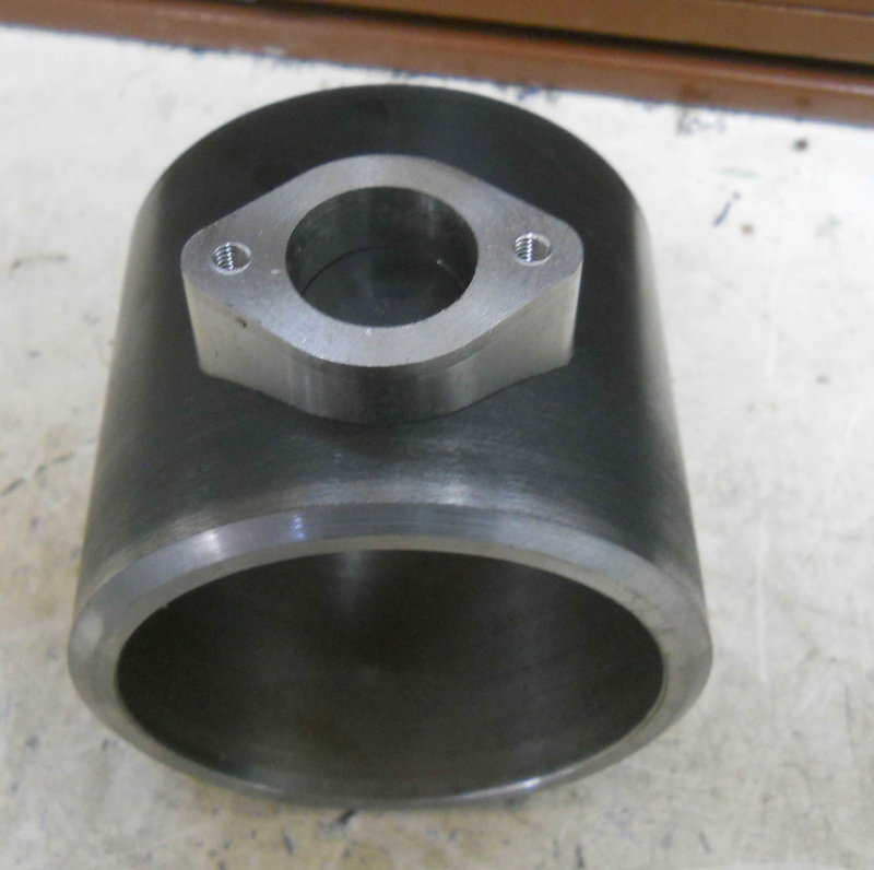 I also made a short tube from 316 that will be welded both to the flange and to the inside of the can, making it steam tight. |
|
|
|
Post by kvom on Oct 1, 2012 17:07:37 GMT -5
Seems I need to start over on the steam dome canister, so I will make it one piece rather than needed to weld on the flange. I drove down to Metal Supermarkets today and browsed their drops area. I found this chuck of HRS, 4"x4"x3.5" (56 cubic inches). It will be machined into a cylinder with OD 3.375" and ID 2.375" (15.8 cubic inches). So that block is 72% swarf to come. I could program almost all of the work on the CNC mill, but I don't have endmills that are long enough. So I will likely rough mill the block to a cylinder and then do most of the rest on the lathe. I'm still thinking about the best steps.  |
|
|
|
Post by kvom on Oct 5, 2012 17:28:05 GMT -5
Decent progress on my "hunk-o-steel". First op was to face mill 1/2" off one of the long sides to get a 3.5x3.5x4 oblong. Next center drilled both ends for later lathe work. Now milled off the corners lengthwise to get an octagonal cross section. Next drilled and tapped a 1/4-20 hole 1/2" deep in one end, screwed in a SHCS, and cut off its head. Now I had this:  On to the lathe between centers, using the screw shank as a dog driver. Then lots of small interrupted cuts until round, and a final cut to 3.375" diameter:  Back to the CNC mill to cut a pocket in soft jaws to hold the cylinder"   Next session I will use this setup to drill a through hole in the center using a succession of drill from 1/8-1" by eighths. Since the work is 4" long, I plan to run a drill half way, then reverse the work in the vise and repeat the op. Then it will be back to the lathe to bore out to the final dimension. Alternatively I may use the boring head. |
|
|
|
Post by GregMiller on Oct 6, 2012 9:22:58 GMT -5
I have not seen a 'built in' dog driver before, clever.
Hope I can remember that tip for future use.
Greg
|
|
|
|
Post by kvom on Oct 7, 2012 17:51:55 GMT -5
The through drilling went fine as foreseen through 5/8" diameter. When I tried 3/4" drill there was not enough torque and the drill stalled the motor (prescribed RPM was 400). I decided to see if I could mill out the bore rather than hand a heavy piece on the lathe with no end support. Some years ago I bought a lot of endmills online, and there were several > 1/2" in diameter. I found one 5/8" 4-flute mill with 2" flutes, so decided to try that. Using the G-wizard feed&speed calculator, I decided on a .25" radial engagement and a .04" ramped depth of cut, which allowed 1020 RPM and 15 ipm feed. This worked out to be pretty easy on the tool (no chatter), and about 40 minutes to mill 2" deep from both sides.  Here's progress to-date:  The bore is large enough to clear the valve body and the walls are a bit thicker then .5". Any further enlargement can be done on the lathe. I also went over to visit a friend who offered to silver solder my copper tube/brass flange since he had a turbo torch. Alas, both propane and Mapp gas failed to generate enough heat. I'm going to try it again with the oxy-acetylene torch later. |
|

