|
|
Post by Ed Hume on Sept 5, 2009 19:48:18 GMT -5
Well guys, I applied my gear cutting knowledge gained from making the Climax to making a set of stainless bevel gears for a 3 truck shay. These have a 39::19 tooth ratio so the teeth will wear and lubricate evenly. Stock drive products does not offer steel gears near this size, and certainly not stainless. Here is a photo from my set on Flickr: ( www.flickr.com/photos/edhume3/sets/72157614192042835/) 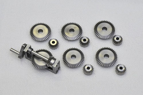 Looks like a good weekend no matter which team wins the football game! Ed |
|
|
|
Post by pkastagehand on Sept 7, 2009 11:27:08 GMT -5
As a gentleman on one of the other sites often says: "Too much fun!"
I keep thinking I'd like to try gear cutting some day but haven't gotten there yet... have the dividing head but no cutters. The cheap approach would be a fly cutter.
Did you custom grind a fly cutter or spring for the involute cutters?
Paul
|
|
|
|
Post by Ed Hume on Sept 7, 2009 12:42:13 GMT -5
Paul, Neither one - I used the techniques that Kozo shows in the Climax book to make my own cutters from tool steel. First you make circular cutter with a curve that approximates the gear tooth at the 20 deg pressure angle, and then you use the circular cutters to make tooth form cutters. Kozo describes making a single edge cutter that can be flipped over to cut the other gear tooth side. He mounts it off-center which provides relief of the cutting edge. I took his instructions and ideas and made an 8 edge circular cutter which allowed me to mill faster. Here is a photo of the cutter on a shop-made holder: 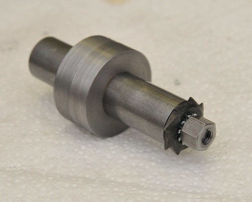 Here is the single edge, off-center cutter which is the style Kozo describes: 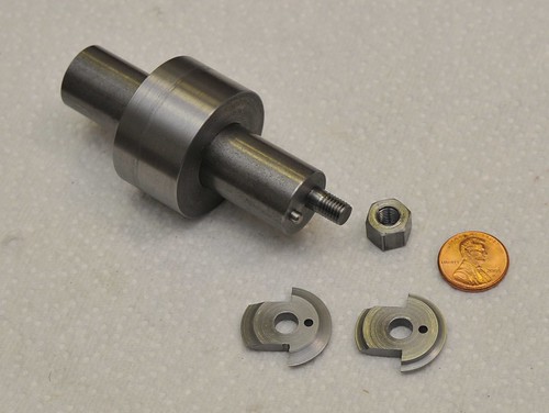 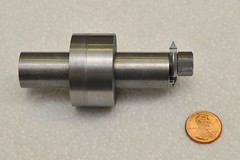 These photos are from my set on flickr www.flickr.com/photos/edhume3/sets/72157614192042835/Ed |
|
|
|
Post by Dan Rowe on Sept 8, 2009 8:40:29 GMT -5
Hi Ed, Nice work on the gears. That cutter is a sweet piece of work. For those who do not know how to draw an involute curve and even for those who do the gear generator I found on the web the other day makes the job really simple. See: woodgears.ca/gear_cutting/template.htmlNotice the HPGL download feature this is plotter language and can be imported into most CAD programs. Ed why did you make the hole in the big gear so small? For all the designs I have seen the right axle bearing has to be in the center of the big gear. The first truck I made with SDP gears had a really short right axle bearing. Since then I have bored out the center. Dan |
|
|
|
Post by Ed Hume on Sept 8, 2009 18:53:09 GMT -5
Dan,
We missed you Saturday.
Kozo's new shay design has an 8mm hole in the large gear for the axle to poke through. The gears I made have a proportionally larger hole, 5/16" diameter versus 1/4" scaled, so that I could re-use some of the fixtures from the Climax project. The annular gap will be completely covered up when assembled in the truck. Most of the gear backside/hub is machined away and then it is mounted on the wheel using three flat head screws in countersunk holes. So there also needs to be a ring of metal surrounding the center hole for the mounting screws.
Ed
|
|
|
|
Post by Harlock on Sept 9, 2009 14:45:39 GMT -5
|
|
|
|
Post by Dan Rowe on Sept 9, 2009 15:57:10 GMT -5
Ed,
I totally forgot about Saturday until I read your post here and I had to slap my forehead.
I knew you had a plan, I just had to ask.
I think that I am going to draw the gears in 3D then have then printed in SS. That way they will look exactly like a Lima gear and bolt to the wheel with a flange. The gear generator will be a really big help for a 3D gear drawing.
Mike, nice...I have to get back to Cass sometime soon.
Dan
|
|
|
|
Post by Harlock on Sept 9, 2009 16:02:24 GMT -5
Dan, let me know how your printed gears work out. You think there will be enough resolution in the process? More and more RP outfits are doing metals now, so it's an up-and-coming thing. I wonder if it will completely replace machining at some point this century...
|
|
|
|
Post by Dan Rowe on Sept 10, 2009 6:59:44 GMT -5
Mike, The resolution for SS at the firm I am thinking about using for SS is 0.1mm. I think that will be more accurate than I could machine the gears. I plan to use a scale tooth length which is impossible to find in modern gears. The profile along the whole tooth flank will be the correct curve not an approximation so yes I think that will be accurate enough. See: www.shapeways.com/The advantage of using them is other people can order the gear for their own use. Dan |
|
|
|
Post by Harlock on Sept 10, 2009 18:23:43 GMT -5
Mike, The resolution for SS at the firm I am thinking about using for SS is 0.1mm. I think that will be more accurate than I could machine the gears. I plan to use a scale tooth length which is impossible to find in modern gears. The profile along the whole tooth flank will be the correct curve not an approximation so yes I think that will be accurate enough. See: www.shapeways.com/The advantage of using them is other people can order the gear for their own use. Dan Excellent. Looking forward to seeing pictures.  Hope you have a macro lens I have seen that site posted in another forum. As a solidworks user myself, I could see taking advantage of it for various things in the future. For now, I am following the book on creating everything so as to learn how to do it. --Mike |
|
|
|
Post by Dan Rowe on Dec 2, 2009 13:01:45 GMT -5
I managed to draw Shay gear set #23 in 3D using ViaCad. It took a bit more time untill I solved the manifold problems so Shapeways would accept the drawing. It does not meet the 3mm minium wall thickness that they say is needed for stainless steel but they allowed me to place an order for the gear. So we will see if they can produce a 7/8ths scale version of the gear. 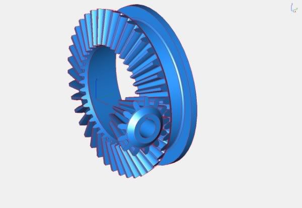 Shapeways does not have wax as a 3D printing option but I have found other firms that offer 3D wax printing, so that might be a good method to make a pattern for casting silicon bronze gears in my shop. Dan |
|
|
|
Post by Harlock on Dec 2, 2009 18:03:03 GMT -5
Cool. Can't wait to see the results.
|
|
|
|
Post by Dan Rowe on Dec 21, 2009 23:06:03 GMT -5
Here is a photo of the first lost wax casting I made. It was wax pattern made from a rubber mold of a Stock Drive Products gear. It is next to a 7/8" scale Lima Shay gear #23 in black plastic. 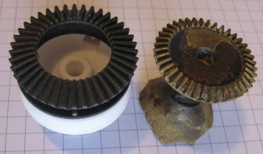 The gear in stainless came today ;D 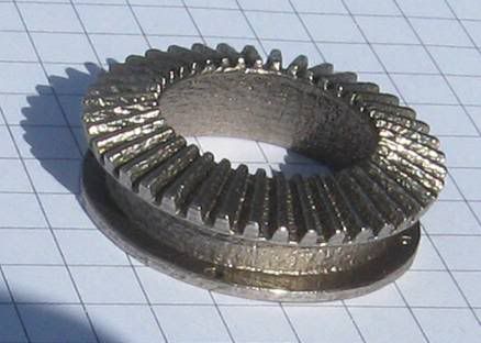 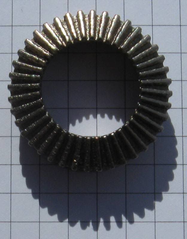 It has a few extra blobs of metal and the faces of the teeth are a bit rough but this is a Shay and I think that the correct size gear is really important... now If I can get the steam engine built and running. For the stainless specs see: www.shapeways.com/topics/udesign/materials/stainless_steel/specifications_of_shapeways_metal.pdfDan |
|
|
|
Post by Harlock on Dec 22, 2009 2:36:14 GMT -5
How big are those squares on the background?
|
|
|
|
Post by Dan Rowe on Dec 22, 2009 7:47:39 GMT -5
Mike,
The paper grid is 1/4" squares. Notice the shadow of the lower photo. I used the light to maginify the worst of the problems on the teeth.
Dan
|
|


 Hope you have a macro lens